I'm continuing here an almost 8 year old story:
http://pakahuszar.blogspot.com/2014/09/engineer-joke.html
http://pakahuszar.blogspot.com/2014/10/engineer-joke-continuance.html
Just in nutshell, what happened since:
I left the oscilloscope, as is for additional three years, without touching it. Unfortunately the processor board gone from the eBay, so I didn't buy it.
After this three years. I brought it to a friend, who run a repair shop. He found some issues in the high voltage PSU, repaired it. Later he started to blame the I2C bus, as it has some problems, what hold the entire control, and didn't able to pinpoint it. Once he will go back and put more effort into it.
The whole thing got forgotten. A few weeks ago, I went to him to pickup some of my donor audio equipment, and picked up the oscilloscope with it. So it is now in my new lab.
Switched it on. The errors are the same. So it not get worse in the last years, what is great from a standpoint.
With the I2C bus error in my mind. I started to go over of the schematics of the oscilloscope (just the analog board is 18 A3 pages itself - Jesus!).
Collected all of the I2C bus connected ICs from all of the boards into an Excel sheet, with the connection points need to cut for troubleshooting. One thing started to get clear during the schematics reading. Let me explain:
If I would design something with I2C control, I would put the I2C capable ICs on the bus, with different addresses and that's it. Philips did it a bit differently. There are some ICs (TTL compatible serial-to-parallel shift registers mainly), what is not I2C compatible, just connected to the I2C lines and has additional control signals (it is weird to my taste, but this is the case).
Also I realized that the front panel board has no I2C connections. It is connected to the processor via a parallel bus.
In the view of the information above, I started to reevaluate the "I2C bus has a problem" sentence.
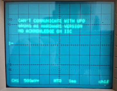
Go through the errors on the screen, one-by-one:
- "NO BATTERY BACKUP" - Irrelevant, it needs 3 AA cells what is not inserted yet
- "WRONG A1 HARDWARE VERSION" - It is checked with one of the shift registers mentioned above. It can be else than the I2C bus as it has different control signals
- "CANNOT COMMUNICATE WITH UFO" - The front panel is not I2C, so it definitely not I2C related
- "NO ACKNOWLEDGE ON I2C BUS" - It can be I2C related, but... If something hold the I2C bus because of the dual purpose mentioned above, can be something else also
If we assume, there is only one error causing all of the problems (likely, but not for sure), it lead us to a different direction. The A3 processor board contains a 74HCT259 providing reset for the UFO and control signals for the I2C connected non-I2C ICs. It is the first what I suspect instead of any I2C ICs.

Without logic analyzer, I wouldn't touch it further.
According the service manual, there is a raiser card exists for measuring things: 5322 218 61479
Looking on the internet, nothing come up on it. There is no other reference than this manual. Not a photo, an expired auction, an internet archive page. It virtually doesn't exists.
On the other side, it is not a highly specific thing. I redesigned it, based on the available information, according to my needs:


Nincsenek megjegyzések:
Megjegyzés küldése