The internet sources suggest to use wsl -l -v but that just show the running Linux instances. If you install it with the command above, the list will be empty.
2024. december 4., szerda
WSL Idiocracy 1. - Check if installed
The internet sources suggest to use wsl -l -v but that just show the running Linux instances. If you install it with the command above, the list will be empty.
2024. szeptember 4., szerda
Terraform, AzApi, Sql Managed Instance, DTC and it's consequences
I got an assignment to enhance out Azure SQL Managed Instances Terraform deployment module with DTC (Yes, it is a good question, why on earth this outdated technology is still needed).
For the DTC you will need two resources added to your managed instance. One is the DTC configuration, the other is the serverTrustGroup what determine which of your managed instances trust each other for the distributed transaction.
As I not even surprised, none of the above exists in the Terrafrom AzureRM provider, so you need to use AzAPI provider for it.
The DTC setting itself is a piece of cake - if you have experience using the AzAPI resources you can easily handle it.
The trustGroup is a different animal.
Here you can find the Microsoft documentation for it: https://learn.microsoft.com/en-us/azure/templates/microsoft.sql/2023-05-01-preview/locations/servertrustgroups?pivots=deployment-language-terraform
You just add the resource and done...
resource "azapi_resource" "symbolicname" {
type = "Microsoft.Sql/locations/serverTrustGroups@2023-05-01-preview"
name = "string"
parent_id = "string"
body = jsonencode({
properties = {
groupMembers = [
{
serverId = "string"
}
]
trustScopes = [
"string"
]
}
})
}
Not exactly. The name, groupMembers, trustScopes are explained in the documentation. The parent_id is not exactly. The documentation said:
"The ID of the resource that is the parent for this resource.
ID for resource of type: locations"
What this means to you?
Usually in the Azure "location" is used as the synonym of "region" - here: wrong
Even, if it would be the region, where should it be located in the management group/subscription/resource group hierarchy?
Anyway, as a normal Azure resource, it should be located in a resource group. Ok, add the resource group ID there. The Terraform give back this error:
"Error: `parent_id is invalid`: expect ID of `Microsoft.Sql/locations`"
What a hack is this Microsoft.Sql/locations ?
Looked through the internet. Yes it is part of the object hierarchy of the serverTrustGroups but, as resource it doesn't exists.
Ok. Deploy the Trust Group manually. Done it. On the portal you can't see the JSON of it.
Try other way.
Try to get it back via AZ CLI:
az sql stg list -g <resource group name> --instance-name <name>
The result:
[
{
"groupMembers": [
{
"serverId": "/subscriptions/00000000-0000-0000-0000-000000000000/resourceGroups/<resource group name>/providers/Microsoft.Sql/managedInstances/sql-test-01"
},
{
"serverId": "/subscriptions/00000000-0000-0000-0000-000000000000/resourceGroups/<resource group name>/providers/Microsoft.Sql/managedInstances/sql-test-02"
}
],
"id": "/subscriptions/00000000-0000-0000-0000-000000000000/resourceGroups/<resource group name>/providers/Microsoft.Sql/locations/West Europe/serverTrustGroups/trust-group",
"name": "trust-group",
"resourceGroup": " <resource group name>",
"trustScopes": [
"GlobalTransactions",
"ServiceBroker"
],
"type": "Microsoft.Sql/locations/serverTrustGroups"
}
]
Now, can you see?
After this, our code will look like something this:
resource "azapi_resource" "trust-group" {
type = "Microsoft.Sql/locations/serverTrustGroups@2023-05-01-preview"
name = var.trust_group_name
parent_id = "${var.resource_group_id}/providers/Microsoft.Sql/locations/${var.region}"
body = jsonencode({
properties = {
groupMembers = [for ServerID in var.groupMembers : { "serverId" = ServerID }]
trustScopes = var.trustScopes
}
})
}
And I try not to judge the quality of the Microsoft documentation ...
2022. május 28., szombat
Fluke (Philips) PM3082 Oscilloscope Repair 1.
I'm continuing here an almost 8 year old story:
http://pakahuszar.blogspot.com/2014/09/engineer-joke.html
http://pakahuszar.blogspot.com/2014/10/engineer-joke-continuance.html
Just in nutshell, what happened since:
I left the oscilloscope, as is for additional three years, without touching it. Unfortunately the processor board gone from the eBay, so I didn't buy it.
After this three years. I brought it to a friend, who run a repair shop. He found some issues in the high voltage PSU, repaired it. Later he started to blame the I2C bus, as it has some problems, what hold the entire control, and didn't able to pinpoint it. Once he will go back and put more effort into it.
The whole thing got forgotten. A few weeks ago, I went to him to pickup some of my donor audio equipment, and picked up the oscilloscope with it. So it is now in my new lab.
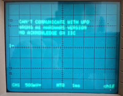
Switched it on. The errors are the same. So it not get worse in the last years, what is great from a standpoint.
With the I2C bus error in my mind. I started to go over of the schematics of the oscilloscope (just the analog board is 18 A3 pages itself - Jesus!).
Collected all of the I2C bus connected ICs from all of the boards into an Excel sheet, with the connection points need to cut for troubleshooting. One thing started to get clear during the schematics reading. Let me explain:
If I would design something with I2C control, I would put the I2C capable ICs on the bus, with different addresses and that's it. Philips did it a bit differently. There are some ICs (TTL compatible serial-to-parallel shift registers mainly), what is not I2C compatible, just connected to the I2C lines and has additional control signals (it is weird to my taste, but this is the case).
Also I realized that the front panel board has no I2C connections. It is connected to the processor via a parallel bus.
In the view of the information above, I started to reevaluate the "I2C bus has a problem" sentence.
Go through the errors on the screen, one-by-one:
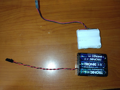
- "NO BATTERY BACKUP" - Irrelevant, it needs 3 AA cells what is not inserted yet
- "WRONG A1 HARDWARE VERSION" - It is checked with one of the shift registers mentioned above. It can be else than the I2C bus as it has different control signals
- "CANNOT COMMUNICATE WITH UFO" - The front panel is not I2C, so it definitely not I2C related
- "NO ACKNOWLEDGE ON I2C BUS" - It can be I2C related, but... If something hold the I2C bus because of the dual purpose mentioned above, can be something else also
If we assume, there is only one error causing all of the problems (likely, but not for sure), it lead us to a different direction. The A3 processor board contains a 74HCT259 providing reset for the UFO and control signals for the I2C connected non-I2C ICs. It is the first what I suspect instead of any I2C ICs.
Without logic analyzer, I wouldn't touch it further.
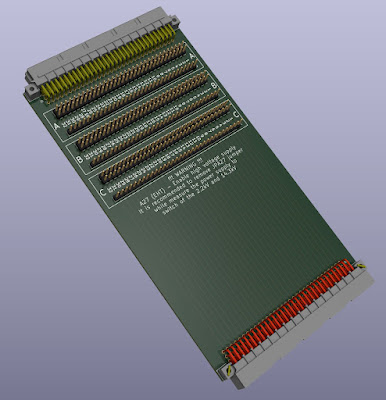
According the service manual, there is a raiser card exists for measuring things: 5322 218 61479
Looking on the internet, nothing come up on it. There is no other reference than this manual. Not a photo, an expired auction, an internet archive page. It virtually doesn't exists.
On the other side, it is not a highly specific thing. I redesigned it, based on the available information, according to my needs:
2022. január 4., kedd
HP E1300A - EPIC Fail
In the last few days I was working on my instrument control software. I wanted to test, what I achieved with an SCPI compliant device also (now I mainly use my Keithley 199 DMM for the tests).
The first SCPI compliant device I found around is a HP E1300A B-size WXI mainframe with DMM and switch cards (I've three of this).
First I wanted to clean it up, repair if it necessary.
(Read further, text continue after the first set of pictures)
Everything is clean, the dead battery pack exchanged to a battery holder. The only thing still need exchange the old Papst fan. Actually the same fan still in production but it cost insane $60 (I got the two E1300A units as a gift, and bought my first one for $15). This one if it is new has 36dB noise level. I found a Noctua model, with the same airflow 17dB noise level. I know it is not the "industrial" one, but the unit will be lightly used in my lab, so it will be good enough. Even the fan isn't installed yet.
Just for the try switched on the unit connected a GPIB adapter and checked if I can communicate with it. Looks everything fine after assembly.
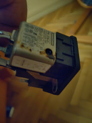
Switched off the unit and went to the bathroom. I hear some weird noise from there. Went back to my room. Thick smoke coming out from the switched off unit and stinking like hell. Pulled out the mains cable and didn't understand what happened.
Disassembled the whole unit once more:
The filter in the mains outlet blown.
At least this indicate, that probably the unit itself doesn't has further issues as result of this failure.
New outlet ordered, I'll finish the assembly when arrived.
2020. április 25., szombat
GP-IB 5. - V2.0 Board
Prelude
I already have several GPIB boards on my desk. Actually I have 1.0, 1.1 (and now 2.0) version of my board. One of the 1.0 boards doesn't work correctly. I meant, I need some diagnostics into the firmware to track down the problem. So I wrote a diagnostics extension to the current instruction set. It is able to manipulate the GPIB pins directly (I tried to resolve the error of this board, but the results were inconclusive).
v2.0 Board
To step forward, I soldered in the next generation board. It also need some software modification as it use ATMEGA32U4 instead of the ATMEGA328P on the previous one.
Everything went easy. Too easy.
The ISP programming was successful immediately. The software modifications took less than five minutes. The board upload worked, just right after fixing one single easy to handle bug.
Connected to my test HP3478A multimeter. Run a scan command. It immediately found the instrument and reported back the reading. The only gotcha was the reading characters appeared one by one slowly.
Next day - troubleshoot
I was thinking one unsoldered pin, and reading timeout cause the problem.
Fired up the diag mode, and realized that the D1, IFC, SRQ and ATN always reporting back high logical level, whatever I do.
Tracking down the issue - playing with the other boards - just came out, that the diag mode doesn't handle certain pins correctly. Modified the diag mode. It resolved the issues on the 1.0 and 1.1 boards, but not on this one. The D1 and the ATN issue remained.
Later on, somehow I figured out that those are used on the Arduino Leonardo board (what I was using as configuration and the bootloader of it) as RX and TX LEDs for the USB communication. Holly shit.
Redesign or fight?
The dilemma came here. I've two options:
Either I redesign the board, and send to manufacturing once more, or fight with the Ardunio bootloader, core, whatever. I chose to fight. Reasons:
- Design and manufacturing has costs, and need several days (or even weeks) until the new board arrive
- The ATMEGA32U4 has two externally accessible full 8 bit ports. Those can be used for faster communication with direct port manipulation. Unfortunately those LEDs are use one pin of each of this ports. So if I don't use them, I lose the speed here.
- Digging deep is fun. I can learn a lot from it.
Blame the bootloader
Actually I don't know why, maybe I read something on a forum, I was thinking, I need to modify the bootloader, and it will resolve the problem (maybe the serial use it for the communication, I don't know)
New bootloader
First of all Identified the source code of the bootloader. It is located here (https://github.com/arduino/ArduinoCore-avr/tree/master/bootloaders/caterina). Checked the Makefile it also need a library called LUFA for the USB communication. I also checked this out. Added the latest Win64 compatible avr-gcc and make.
I tried various ways to point the Makefile to the LUFA, all of my attempts failed. Also it missed grep tool. I felt like the Windows is a dead-end for this build.
Switch to Linux
Didn't wanted to build a linux machine, or add a Hyper-V based Linux. So I fired up the Subsystem for Linux and installed the Ubuntu 18.04LTS from the Microsoft Store.
Installed avr-gcc, build tools, make, etc. on it.
Found the filesystem location of the Ubuntu in the Windows filesystem and copied the source code over.
It wasn't work. I got various permission issues with the copied files, so I gave up and cloned the repos once more.
Trying to compile gave the same errors as on Windows without the grep problem. After several path modifications, adding the USB VID and PID finally it started the build. The result was a catastropy:
The bootloader in question was built last time 8 years ago. Both the avr-gcc and the LUFA library stepped forward since.
Figured out what tag was used originally, switched the repo to it. Now the bootloader compiled successfully.
Testing with the new bootloader
I didn't wamt to hack it into the Arduino IDE so I flashed the bootloader manually to my board. Uploaded the code also. And....
and it failed.
Hack the core?
No. Even I figured out that the problem is probably in the USBCore.c, I didn't wanted to hack it. It wouldn't create a future proof solution.
Looking around and thinking lead me to create a custom Arduino board specification for my project.
New board config - not yet
First of all I wanted to have something I can learn from. I found an ATMEGA32U4 based custom board from ArachnidLabs (http://www.arachnidlabs.com/tsunami/), and the git repository for it: https://github.com/arachnidlabs/arachnidlabs-boards
It turned out immediately that I need a stable place to to host the json and the package zip. Something I can count on that will be there for a while. Something can be accessed without any authentication voodoo (like OneDrive).
As the AVR-GPIB project of mine hosted on GitLab, I was looking around there. As Github has Github pages, what a surprise, GitLab has GitLab pages.
I read through the documentation, it was still not clear, how to setup the GitLab pages.
Created a repo named suf.gitlab.io, put the files in there. Nothing happened.
Ok, it looks like I need a gitlab-ci.yml for building the site. This isn't surprising concept to me, as in the last few years I'm working as DevOps engineer. Writing Jenkins CI/CD pipeline scripts on daily bases.
Wrote the script, pushed the repo, failed. Some naming wrong. Corrected.
Next. Building correctly. The site still give 404 back.
After many tries realized, that my files from the GPIB subdirectory landed into the root of the site. I was thinking that it is because the root has no files in it, just the GPIB folder. So added an index.html.
The previously successful build failed again.
After reading many things, several trials, came out, that the only approach what is working, to add everything to a newly created temporary folder and rename (mv) it to public, what is the designated name of the publishing.
So my GitLab pages site born: https://suf.gitlab.io
It is small, it is yellow, it is sour, but ours (I know it is not got through in English, as it refers to an epic Hungarian movie from '69 - https://en.wikipedia.org/wiki/The_Witness_(1969_Hungarian_film)).
New board config - now really
Created the json, modified the pins_arduino.h (pointing the LEDs to two not externally exposed MCU pins), built the package, created the hash, added into the json, uploaded the whole thing to the GitLab, added the json to the Arduino IDE, went to the board manager and...
nothing happened.
Repaired two things looked like bug: name of the json. I don't know if it is a requirement, or just a kept convention, but renaming don't harm.
Realized, that I didn't change the length of the package file in the json, so now I did it.
Push to GitLab, back to Arduino, my config appeared in the Board Manager
Install: failed. There must be a single folder inside the package.zip.
Changed the required things, push to GitLab. Install now works.
Try to upload the code I wrote.
Getting weird inconclusive errors, communication problems. Switched back to Arduino Leonardo, getting the same errors. It smelled like problems with the Windows COM handling. Reboot resolved it.
Try to upload once more. There are missing avrdude parameters. Various parameter related issues. Finally I added into the package.txt whatever I found. It looks like that the ArachnidLabs config was written for an earlier Arduino IDE what doesn't require those parameters.
Now the board upload works.
Try it out
GP-IB diag functions now work as I expected. We are ready!!!!
Noooooo.
The diag works, the communication with the instruments, not. Enough! Sleep!
Next day
It was something itching in my mind. Tried out the previously working boards. Stopped working those too.
Either my HP 3478A multimeter died, what I'm using for the tests, or the diag modifications what I did in the code later on, disrupted the communication.
Figured out soon: the diag was buggy. Fixed it. Now the v2.0 board works.
End of this story.
Will continue with the further hardware and software development of the GPIB adapter.
2018. szeptember 13., csütörtök
Fake in China (DIY Curve Tracer 4.)
I thought why not try to order it from Aliexpress. For control I also ordered a few from Mouser.
Both devices on the same board:
This device should have 0,25 Ohm maximum on resistance.
2018. augusztus 10., péntek
Farewell to "freedom"
I'm not an idiot. I was working with MSP430, TI Tiva, AVR, ESP8266, Nuvoton ARM MCUs, STM32 (recently) in the recent years. Usually after a few days of learning, struggling I always found the way, but not with those (Kinetis series).
But they did everything to be successful. Erich Styger is writing an excelent blog (mcuoneclipse.com) on it. I learned many things from him. The Freescale was the only company from all of the MCU manufacturers who was organizing local workshops here in Hungary.
Nothing helped. So I give away my assets connected to the Kinetis/Freedom word to the newly founded makerspace: 1337
Stack of the boards waiting on my shelf to the transport.
2018. június 9., szombat
2018. május 31., csütörtök
Titan Struggling
2018. május 6., vasárnap
Home Automation - building docker
My comfort zone if we are talking about linux is mainly Ubuntu and Debian. I heard from various places that I should use Alpine for Docker. Actually I run already into some prebuilt Docker images what based on Alpine during my daily work. So I decided to build this new system on Alpine thinking it is a good opportunity to learn it.
First:
Downloaded the image optimized for virtualization as guest, configured a Gen2 Hyper-V guest and started it.
Yes, it is optimized for virtualization, but not for Hyper-V. Not even started
Second:
Downloaded the standard image. This was able to start in the Hyper-V so, I installed into the vhdx.
As I'm usually copying the image to create a new virtual machine, the Alpine gets here a plus point from me, as it doesn't need boot process tweaking like the Ubuntu for the disk image copying.
Installed nano, as I'll need to edit some config files in the actual machines, and started to replicate the disk images, create additional virtual machines
Third:
I've set the IP address, machine name, DNS, gateway, etc. Just the usuals things.
After reboot it won't start anymore. The reason is the chronyd. As it wasn't able to aquire the time from the internet, waited indefinitely in the boot process. No console, no SSH.
Ok. machine killed, recreated from my base image. Looked around, find nothing. Finally checked the contents of the alpine chronyd package and find out, that I can add the timeout option into the /etc/conf.d/chronyd file. In the ARGS add -t 60
Fourth:
Configured SSH for my needs, added the additional repo for some extra packages needed by the Docker engine.
Installed Docker on all of the x64 machines, setup startup of the Docker
Fifth:
Starting Docker on the machines give this error:
After several attempts I failed to resolve this issue, but find some articles discussing why the Alpine doesn't fit to the task:
http://janhapke.com/blog/alpine-linux-sucks-for-hosting-docker-containers/
http://www.nathanbak.com/?p=37
So I decided. Forget this and go back to Ubuntu. My next try will be on the shiny new Ubuntu 18.04 LTS
2018. május 1., kedd
Robo3D reconstruction
In the last month I had not too much time to work on my projects. I just focused on one thing.
It was almost five years ago that I started my long struggling journey in the 3D printing. At that time my intention was to use the printed parts in my electronics projects and not to involve myself in the technology. This changed since, learned a lot. The main reason is that the printer I bought the Robo3D is a heap of crap. It took me two years to get some acceptable results. Then it broke once more, and I put it to the side until now.
I wanted to have a 3D printer in the office, so I repaired the Robo.
- Printed a new improved Greg's wade extruder
- Designed a new object heater
- Replaced the Z endstop with capacitive sensor (actually works quite well with the glass only bed)
- Replaced the electronics with a completely new Arduino Mega + Ramps + DRV8825 set
- Added a graphic LCD
- Added cooling for the electronics (a computer HDD cooler)
- Built a customized current Marlin for it
- Added a case light (two LED strips to the top)
- Replaced the E3D v6 to a new one (with the cartridge type heather block)
- Replaced most of the cabling
Here is the result, with the first print on the bed:
Just some gluing and cable tightening left for today until I can bring it to the office.
2017. december 10., vasárnap
High Voltage DC Power Supply 4. - The phase switching module
In my previous posts about the high voltage supply I already wrote about the small electronics able to keep the GND of the DC side on earth potential without isolation.
The board design:
Based on this design I ordered the boards from allpcb. Actually I made a mistake around the design. I bought my relays after I sent the board for manufacturing. The result is that I connected the switched circuit on wrong direction. This means if I build the circuit the relays create a short circuit to the mains.
Throw away the boards (without even soldering a single component), ordered a new batch.
It also arrived within a few days:
The finished board:
I wrote a small arduino code to run the board. It has an ATTINY84 in it. Actually the code would fit in an ATTINY24 easily.
Assembled the whole thing into it's final place:
I connected the final thing to the mains. Switched on the power switch. Everything looked fine, until I pressed the output button.
The main circuit breaker in my house went off. Shitt.
Few more tries. The result get even worst. It killed the mains even switching on the power switch and not the output button.
Removed the phase switching board. Measured. It looked like both of the relays killed. There was a short circuit between the line and the neutral on the board.
Here is when Murphy comes into the picture. How many components buy I usually for my circuits? Way more than needed. Except this case. I had only those two relays on the board. Weekend. I should wait until Monday, to replace the relays.
In the meantime I removed the relays from the board - I hate the THT desoldering.
Removed the cap from one of the relays to be able to make a picture of the burnt contacts:
The surprise come here. No burned contact. Even I made a picture with my microscope. The result is the same:
Nothing, the contacts are intact. Measured the second desoldered relay, what still has it's cap. the result is the same, no sign of the failure anymore.
Just my guess that the heat and mechanical torture of removing the relays of the board resolved the temporal latch-up of the contacts.
Now back to the basics. As I can't find out the source of the problem (didn't wanted to play this game with new relays). I just guessed that the inrush current of the capacitors causing the problem (as I wrote earlier, I had problem with it already). So I hacked a solution. Together with the new relays I bought some inrush protector NTCs. It isn't an ideal solution, but hopefully will be sufficient. Hacked a PDU board to accommodate the NTCs. I've a few spare anyways:
The relays replaced. The whole thing works as expected.
I'm still thinking about the proper solution. The device is a tool and not a target for me. So it may not worth the effort to build a second version.


