
2016. december 1., csütörtök
Secret Project 2. - Power Supply
Finally the arrived the small power supply for the LEDs (and the whole project):

2016. november 19., szombat
Secret Project 2.
Two of the boards made during this week is part of my second secret project.
It is based on ESP8266:

As you see I choose the ESP-07 for this, what I've in my parts bin.
I tried to wake up the processor board:

First I loaded the standard Arduino flash test example into it. It was "working", but...
...the result is a massive failure for me:

I bought the ESP-07 modules at the beginning of the ESP8266 era, to play with it. I not even checked the flash size at that time. It has 512K (same as the ESP-01). I changed the flash on the ESP-01, but this has a metal can. Therefore it not worth the effort to change the flash.
Fortunately I've a few ESP-12Es also. So, jumped to my workshop:

Much better:

And ordered a few ESP-07S and ESP-12F.
It is based on ESP8266:

As you see I choose the ESP-07 for this, what I've in my parts bin.
I tried to wake up the processor board:

First I loaded the standard Arduino flash test example into it. It was "working", but...
...the result is a massive failure for me:

I bought the ESP-07 modules at the beginning of the ESP8266 era, to play with it. I not even checked the flash size at that time. It has 512K (same as the ESP-01). I changed the flash on the ESP-01, but this has a metal can. Therefore it not worth the effort to change the flash.
Fortunately I've a few ESP-12Es also. So, jumped to my workshop:

Much better:
2016. november 15., kedd
Electronics - New projects cont...
How the Saturday boards are standing today:

I should write soon, not just taking pictures. :-)

I should write soon, not just taking pictures. :-)
2016. november 12., szombat

2016. október 14., péntek
ESP-01 Surgery
I'm working on ESP8266 projects lately. I wanted to have OTA upgrade working from the beginning. The plan was to upload the new firmware through the web browser into the SPIFFS filesystem (done). Check the upload integrity there (wip). And flash it from there (done). This process require at least the double size of flash than the binary code.
My first working project is ~280K binary. This means that the 512K flash of the ESP-01 module isn't enough.
I was looking around, how can I increase it. I found this blog post:
http://tech.scargill.net/32mb-esp01/
I like the idea of upgrading the flash chip, but I've a few problems with the solution.
So I decided to try to find a 150mil wide 4MByte (32Mbit) flash chip from reliable source.
I found it. It is a Cypress (Spansion) S25FL132K0XMFI041 from TME: http://www.tme.eu/en/details/s25fl132k0xmfi041/fram-memories-integrated-circuits/cypress/
It costs more ($0.75/each) but looks more reliable and no pin bending.
The package arrived yesterday from TME, and I done my first surgery tonight:

The original with the 512K Winbond chip on the left, the Spansion 4M chip on the right.
If you fire the Arduino IDE, You can find the CheckFlashConfig sketch for checking the flash size:

The result is reported to the Serial monitor.
Before the surgery:
 After the surgery:

A few more modules waiting for the operation. :-)
My first working project is ~280K binary. This means that the 512K flash of the ESP-01 module isn't enough.
I was looking around, how can I increase it. I found this blog post:
http://tech.scargill.net/32mb-esp01/
I like the idea of upgrading the flash chip, but I've a few problems with the solution.
- It uses a 208mil wide chip instead of the original 150mil package. I really don't like the bending pin solution
- Few sources said that the Winbond flash chips are not really reliable
- I know it is cheap ($2.08/10pcs) on the eBay, but there is to many fake chips, so I don't like to buy it there (http://www.ebay.com/itm/10pcs-W25Q32FVSSIG-W25Q32FVSIG-25Q32FVSIG-4M-Memory-Flash-SOP-8-SMD-/201098254024)
So I decided to try to find a 150mil wide 4MByte (32Mbit) flash chip from reliable source.
I found it. It is a Cypress (Spansion) S25FL132K0XMFI041 from TME: http://www.tme.eu/en/details/s25fl132k0xmfi041/fram-memories-integrated-circuits/cypress/
It costs more ($0.75/each) but looks more reliable and no pin bending.
The package arrived yesterday from TME, and I done my first surgery tonight:

The original with the 512K Winbond chip on the left, the Spansion 4M chip on the right.
If you fire the Arduino IDE, You can find the CheckFlashConfig sketch for checking the flash size:

Before the surgery:
A few more modules waiting for the operation. :-)
2016. szeptember 18., vasárnap

2016. július 23., szombat
Multimeter nightmare
I've scored a nice 6,5 digit bench multimeter back in December 2014 on the eBay. A Schlumberger Solartron 7061.

I felt, that is a good idea.
It was not.
The root of the problem is the missing test leads.What is the problem with it, you may ask. Go to the shop buy some cheap Chinese leads or spend a fortune on some Fluke or Keysight leads and done.
Unfortunately it is not so simple. Schlumberger used some weird connector instead of the usual banana plugs.
This one:

You can tell: This kind of animal doesn't exists. But it does. It is right on the front of my multimeter.
First of all, I tried to find test leads on the net, on eBay, etc. All of my attempt failed.
After this, I was looking around, what kind of connector is this. Some internet sources told that this is a Mini XLR.
I bought a few of this:
 Won't fit.
Next iteration: reading through various forum posts, I found the exact correct type:
Fischer Connectors S 104 A053-130+
I was looking around, the only place I found it was a US company unknown to me, for SIXTY FIVE bloody dollars. Are you out of your mind? It is just a connector!
Even I should pay the shipping and the customs. NO WAY!
Ok, lets go further.
I went to the Alibaba and later Aliexpress, where I found a company, what manufactures the clone of this Fischer Connector product line, but not this exact pin configuration.
I wrote to them if they are able to produce this connector:

I think it isn't a bad assumption to say, they will never provide this connector to me.
At this point I gave this up for a while...
...beginning of this year I wrote to my list, to handle this issue.
Went back to the US site I found it. They had no stock left. Ouch.
Next try:
Wrote a letter to the manufacturer, if they are able to sell it to me directly.
They directed to me to the Hungarian distributor.
We had a few mails, agreed on the exact product, price.
At the end I forgot to answer their last question about the invoicing.
A few month later it pop into my mind, but didn't wanted to write an apologizing letter. So I let it go.
Final try:
On the first day of my vacation came a newsletter from Farnell, that they are included Fischer Connector products into their portfolio.
Searched immediately, and YES, they have it on stock.
After arriving home, I ordered it, arrived:

Now, I have to create some banana breakout box, test lead, something out of it to be able to use.
P.S.: Just tell me, who on earth is so idiot to design an un-insulated, metal test lead connector to a multimeter with high voltage capability????

I felt, that is a good idea.
It was not.
The root of the problem is the missing test leads.What is the problem with it, you may ask. Go to the shop buy some cheap Chinese leads or spend a fortune on some Fluke or Keysight leads and done.
Unfortunately it is not so simple. Schlumberger used some weird connector instead of the usual banana plugs.
This one:
You can tell: This kind of animal doesn't exists. But it does. It is right on the front of my multimeter.
First of all, I tried to find test leads on the net, on eBay, etc. All of my attempt failed.
After this, I was looking around, what kind of connector is this. Some internet sources told that this is a Mini XLR.
I bought a few of this:

Next iteration: reading through various forum posts, I found the exact correct type:
Fischer Connectors S 104 A053-130+
I was looking around, the only place I found it was a US company unknown to me, for SIXTY FIVE bloody dollars. Are you out of your mind? It is just a connector!
Even I should pay the shipping and the customs. NO WAY!
Ok, lets go further.
I went to the Alibaba and later Aliexpress, where I found a company, what manufactures the clone of this Fischer Connector product line, but not this exact pin configuration.
I wrote to them if they are able to produce this connector:

At this point I gave this up for a while...
...beginning of this year I wrote to my list, to handle this issue.
Went back to the US site I found it. They had no stock left. Ouch.
Next try:
Wrote a letter to the manufacturer, if they are able to sell it to me directly.
They directed to me to the Hungarian distributor.
We had a few mails, agreed on the exact product, price.
At the end I forgot to answer their last question about the invoicing.
A few month later it pop into my mind, but didn't wanted to write an apologizing letter. So I let it go.
Final try:
On the first day of my vacation came a newsletter from Farnell, that they are included Fischer Connector products into their portfolio.
Searched immediately, and YES, they have it on stock.
After arriving home, I ordered it, arrived:

Now, I have to create some banana breakout box, test lead, something out of it to be able to use.
P.S.: Just tell me, who on earth is so idiot to design an un-insulated, metal test lead connector to a multimeter with high voltage capability????
2016. április 14., csütörtök
AutomaTales - ModuleMania
As I'm thinking further, it become obvious that I want to create a modular system. Something like a backplane, with equaly sized modules, the sensors, the actuators, the MCU, and the power source also reside on separate modules.
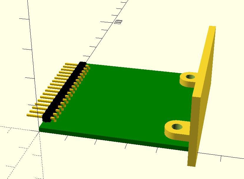
The planed module connector has 1 SPI, 1 I2C and 8 GPIO connections. This is 17 pins together with the two power rails (3.3V and 5V). A 17 pin 0.1" single row header fits onto the 5cm edge of the board.
As I'm going further with it, I came up with quite a few modules, I want to implement. The list isn't complete, and the modules are subject to change:
I also adding parametric 3D printable enclosure for it.
Some of the modules already designed. Although it can be ordered from a fab, but all of the designs ready until today uses single sided board, what can be easily created at home with toner transfer. Most (not all) of the designs uses exclusively trough hole components, what make the life easier.
And this is how the enclosure and the module will fit. My first animation in OpenSCAD!
Even I went further. Designed a box, the backplane and the module form factor already. The modules will be implemented in 5x5cm form factor. Why? Because this can be cheaply ordered from the Chinese PCB factories - ~$10 for 10pcs.
The planed module connector has 1 SPI, 1 I2C and 8 GPIO connections. This is 17 pins together with the two power rails (3.3V and 5V). A 17 pin 0.1" single row header fits onto the 5cm edge of the board.
As I'm going further with it, I came up with quite a few modules, I want to implement. The list isn't complete, and the modules are subject to change:
- Relay - Single channel relay module
- RCR - Module for the rolling code receiver
- Power sensor - Sensing if a mains voltage exists at a particular point
- Temp/humidity - AM2302 based module (the sensor can be fitted internally or connected externally)
- Esp01 - ESP-01 based "brain" module switchable between two GPIOs and an I2C
- Esp07/12 + pcf8574 - ESP-07 or ESP-12 based module with an I2C extender
- Esp12e/f - Questionable. Can be created if the internal flash SPI ports are shareable with external SPI devices easily - testing needed
- Arduino + nrl24l01+ - MySensors.org sensor node "brain"
- PSU - 5V/3.3V capable PSU based on HLK-PM01 and 3.3V LDO or buck converter
- Nrl24l01+ - Nordic communication module - used primary for the Beaglebone to create MySensors.org gateway
- Barometric pressure sensor
- Bus Extender
- Power Meter, Current transformer type
- Power Meter, Hall sensor type
- Power Meter, Utility meter pulse counter
- Gas Utility meter Hall sensor
- SSR Module
- GPIO Module - Isolated I/O Module, a DC/DC converter may added
I also adding parametric 3D printable enclosure for it.
Some of the modules already designed. Although it can be ordered from a fab, but all of the designs ready until today uses single sided board, what can be easily created at home with toner transfer. Most (not all) of the designs uses exclusively trough hole components, what make the life easier.
And this is how the enclosure and the module will fit. My first animation in OpenSCAD!
2016. április 12., kedd
AutomaTales - Mains Voltage Sensor
No, I don't want to measure the mains voltage (yet) here.
I want to build my garage lamp switch as minimally invasive to our current setup, as I can.
What does that mean?
The lamp today is switched by two wall switches (one inside the garage, one in the house at the garage door) in alternating configuration. I want to keep the possibility to operate the lamp with this switches. As I'm not an electrician, I not really want to touch the wires, switches inside the wall (it would be a dirty job anyways). Fortunately I've continuous mains source also at the lamp itself.
So the plan is to connect the remote switching unit to the uninterrupted source and sense if the switches are on or off. This signal will be used to alternate the lamp and not to determine the status. Every time it change (from on to off or off to on), will change the light state.
For the sensing I need some electronics. The mains is not a child play so the proper isolation is crucial.
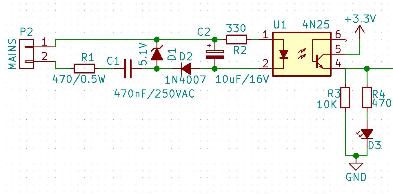
I want to stick to the simplest circuit possible:
A capacitive non-isolated power supply (two caps, two resistors, a diode and a zener) plus an optoisolator. The whole thing cost around $1.
Here is the design:
I want to build my garage lamp switch as minimally invasive to our current setup, as I can.
What does that mean?
The lamp today is switched by two wall switches (one inside the garage, one in the house at the garage door) in alternating configuration. I want to keep the possibility to operate the lamp with this switches. As I'm not an electrician, I not really want to touch the wires, switches inside the wall (it would be a dirty job anyways). Fortunately I've continuous mains source also at the lamp itself.
So the plan is to connect the remote switching unit to the uninterrupted source and sense if the switches are on or off. This signal will be used to alternate the lamp and not to determine the status. Every time it change (from on to off or off to on), will change the light state.
For the sensing I need some electronics. The mains is not a child play so the proper isolation is crucial.
I want to stick to the simplest circuit possible:
A capacitive non-isolated power supply (two caps, two resistors, a diode and a zener) plus an optoisolator. The whole thing cost around $1.
Here is the design:
2016. április 11., hétfő
AutomaTales - Connecting the Heating
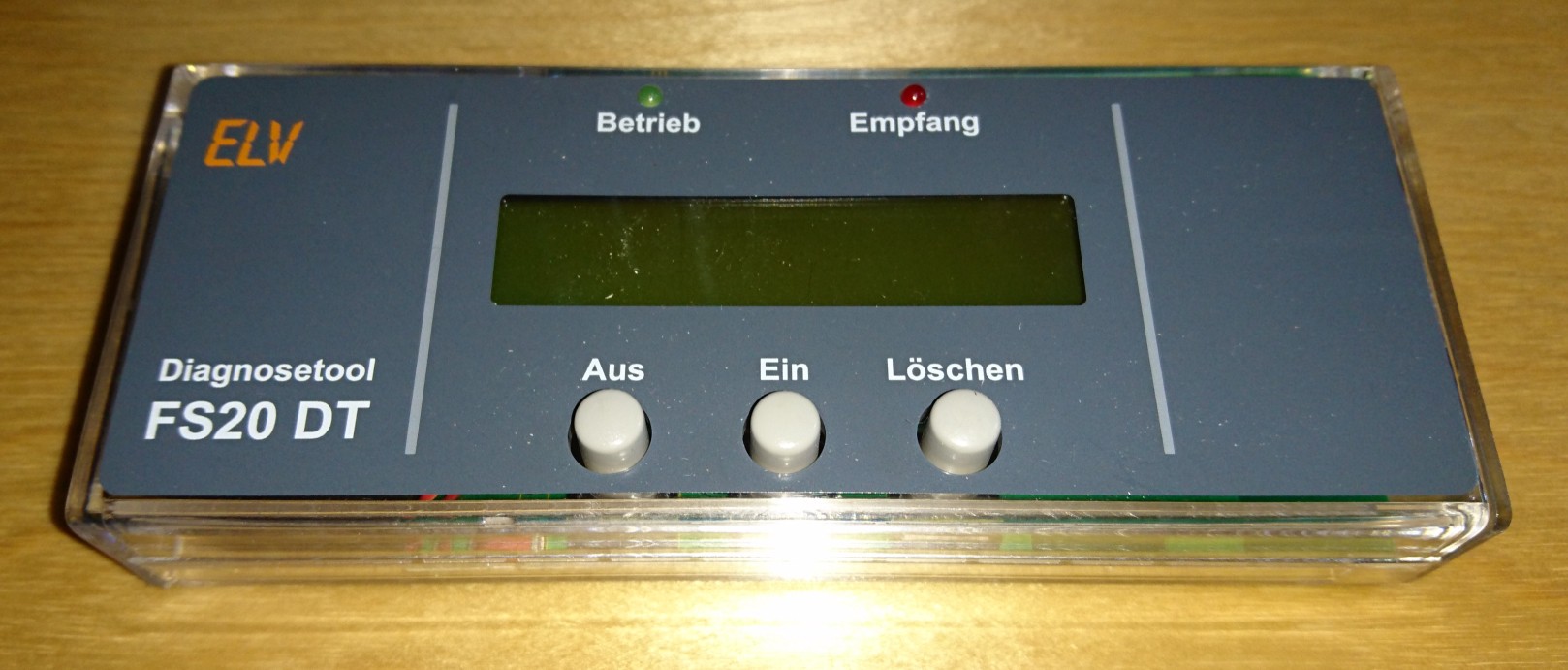
As I mentioned earlier I've several Conrad (ELV) FHT80B thermostats, with radio controlled valves, and I've a CUL v3.2 device. Now I'm try to connect these devices to my OpenHAB.
Before I started to work on this project I updated the firmware in the CUL to the one suggested for OpenHAB from here:
http://culfw.de/culfw.html
The references for the connection can be find here:
https://github.com/openhab/openhab/wiki/FS20-Binding
https://github.com/openhab/openhab/wiki/CUL-Binding
Setting up the binding:
1. Copy the required addons into the /opt/openhab/addons folder:
org.openhab.io.transport.cul-1.8.1.jar
org.openhab.binding.fht-1.8.1.jar
If you have other devices than the heating from the FS20 family you may need theorg.openhab.binding.fs20-1.8.1.jar
also.
2. Edit the configuration file /opt/openhab/configurations/openhab.cfg. Add the following to the end:
This code will be the code of your CUL device and has no connection with the codes of the FHT80b devices. In addition if you want to get readings from your devices, you have to be sure, that the "CEnt" setting in each of FHT80B devices is set to "nA".
3. You have to create some items in your items file for your FHT80B device. Something like this:
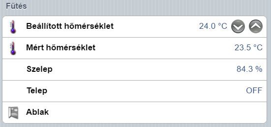
4. Now you have to insert the read values into your sitemap:
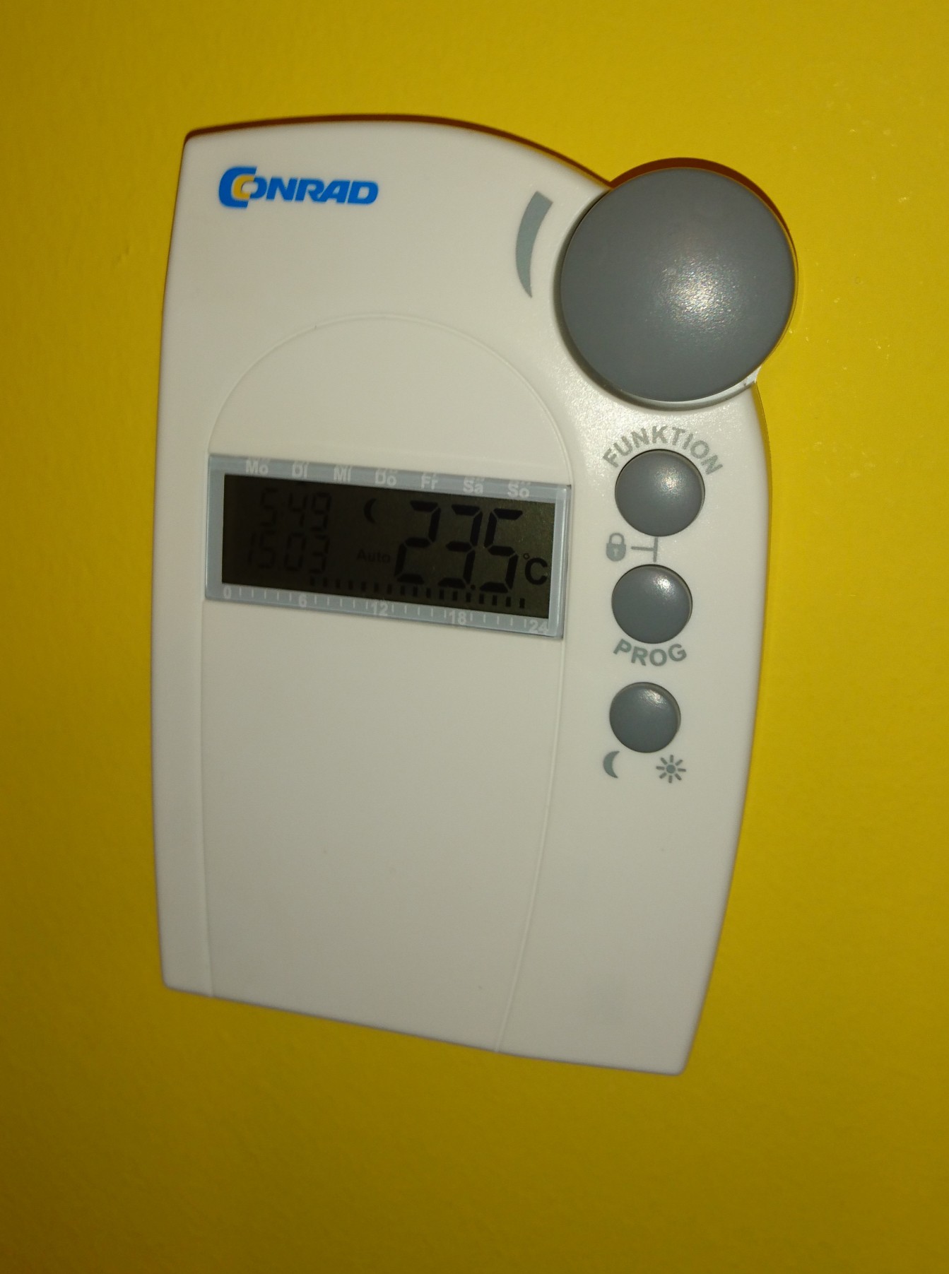
Sorry for the Hungarian text, as this is a real data from my house, I'll translate the whole frontend to Hungarian to my family.
One thing to add: Be patient. Getting the data is a time consuming task. Some of the data will just arrive when changed. So it can take several minutes, or even hours, to get your data.
fht:device=serial:/dev/ttyACM0
fht:baudrate=38400
fht:parity=0
fht:housecode=XXXX
The housecode is your choice. It is a four digit hexadecimal code. And it is absolutely necessary. If you don't provide it here, your system will not start without even a sign of the problem. You can just see the error message when you switch on the debug logging.This code will be the code of your CUL device and has no connection with the codes of the FHT80b devices. In addition if you want to get readings from your devices, you have to be sure, that the "CEnt" setting in each of FHT80B devices is set to "nA".
3. You have to create some items in your items file for your FHT80B device. Something like this:
Number fhtRoom1Desired "Desired-Temp. [%.1f °C]" { fht="housecode=552D;datapoint=DESIRED_TEMP" }
Number fhtRoom1Measured "Measured Temp. [%.1f °C]" { fht="housecode=552D;datapoint=MEASURED_TEMP" }
Number fhtRoom1Valve "Valve [%.1f %%]" { fht="housecode=552D;address=00;datapoint=VALVE" }
Switch fhtRoom1Battery "Battery [%s]" { fht="housecode=552D;datapoint=BATTERY" }
Contact fhtRoom1Window "Window [MAP(en.map):%s]" { fht="housecode=52FB;address=7B;datapoint=WINDOW" }
The housecode in the example is the code of the FHT80B device itself. You can read it from the device, the code1 is the first part, the code2 is the second part, and you must convert your readings to hexadecimal.4. Now you have to insert the read values into your sitemap:
Frame label="Heating"
{
 Setpoint item=fhtRoom1Desired minValue=6 maxValue=30 step=0.5
 Text item=fhtRoom1Measured
 Text item=fhtRoom1Valve
 Text item=fhtRoom1Battery
 Text item=fhtRoom1Window
}
The result is something like this:
Sorry for the Hungarian text, as this is a real data from my house, I'll translate the whole frontend to Hungarian to my family.
One thing to add: Be patient. Getting the data is a time consuming task. Some of the data will just arrive when changed. So it can take several minutes, or even hours, to get your data.
2016. április 10., vasárnap
Repair: HP 3478A
The metallized film capacitors are self-healing types as we know.
Yes, I see:

Yes, I see:

Mains line RIFA filter cap of the HP 3478A Multimeter
AutomaTales - Switching the Lamp (a LED)
Going further. This is just a copy-paste programming.
I grabbed the Arduino code from here:
http://iot-playground.com/blog/2-uncategorised/40-esp8266-wifi-relay-switch-arduino-ide
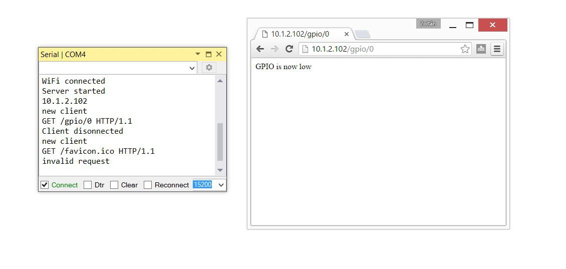
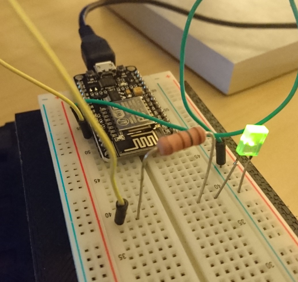
Changed the SSID and the password, connected a 150ohm resistor and the first LED I found in my junk box to the corresponding pins of the ESP8266. Downloaded the code, and fired the serial monitor in the Visual Studio:
When I connect to the web server from a browser, I can switch the LED on and off.
Now integrate it to the OpenHAB.
We don't need anything else just modify the previously created rules. First I just added the http calls into the previously created rule, but the result wasn't satisfactory. I was able to control the LED from the remote, but not from the web browser. So I modified it a bit more.
Here is the result:
I grabbed the Arduino code from here:
http://iot-playground.com/blog/2-uncategorised/40-esp8266-wifi-relay-switch-arduino-ide
Changed the SSID and the password, connected a 150ohm resistor and the first LED I found in my junk box to the corresponding pins of the ESP8266. Downloaded the code, and fired the serial monitor in the Visual Studio:
When I connect to the web server from a browser, I can switch the LED on and off.
Now integrate it to the OpenHAB.
We don't need anything else just modify the previously created rules. First I just added the http calls into the previously created rule, but the result wasn't satisfactory. I was able to control the LED from the remote, but not from the web browser. So I modified it a bit more.
Here is the result:
import org.openhab.core.library.types.*
import org.openhab.core.persistence.*
import org.openhab.model.script.actions.*

rule "GarageLightRemote"
when
    Item KeeLoq_Remote_B changed from CLOSED to OPEN
then
    if(Garage_Light.state == ON)
    {
        sendCommand(Garage_Light, OFF)
    }
    else
    {
        sendCommand(Garage_Light, ON)
    }
end

rule "GarageLightOffAction"
when
    Item Garage_Light changed from ON to OFF
then
        sendHttpGetRequest("http://10.1.2.129/gpio/0")
end

rule "GarageLightOffAction"
when
    Item Garage_Light changed from OFF to ON
then
        sendHttpGetRequest("http://10.1.2.129/gpio/1")
end
Here is the circuit:2016. április 9., szombat
AutomaTales - ESP8266, Arduino, Visual Studio
I'm not a big fan of the whole Arduino ecosystem. The hateful IDE, and the lack of the debug-ability kept far from it.
On the other side I must admit that it is evolved since my first encounter, and it looks like something unavoidable.
I need some remote sensors, actuators, for my OpenHAB system. I want to build most of them. As I looked around, I seen two easily usable solution:
As I heard the LUA interpreter of it not really fits into bigger project, so I chosen the Arduino framework for it. Actually I'm just learning it, so I don't know where this lead to.
My first goal to be able to switch a GPIO of the ESP8266 via a HTTP REST API interface.
As I mentioned above I really hate the Arduino IDE. I run into various problems with it when I tried to configure and compile the Marlin firmware for my 3D printer. Then I found that you can use the trusted Microsoft Visual Studio (I'm using it for my daily work and a few contract projects) with this addon:
http://www.visualmicro.com/
for the task.
Putting together the environment:
On the other side I must admit that it is evolved since my first encounter, and it looks like something unavoidable.
I need some remote sensors, actuators, for my OpenHAB system. I want to build most of them. As I looked around, I seen two easily usable solution:
- ESP8266 based WiFi modules
- MySensors.org NRF24L01+ and Arduino based mesh network
As I heard the LUA interpreter of it not really fits into bigger project, so I chosen the Arduino framework for it. Actually I'm just learning it, so I don't know where this lead to.
My first goal to be able to switch a GPIO of the ESP8266 via a HTTP REST API interface.
As I mentioned above I really hate the Arduino IDE. I run into various problems with it when I tried to configure and compile the Marlin firmware for my 3D printer. Then I found that you can use the trusted Microsoft Visual Studio (I'm using it for my daily work and a few contract projects) with this addon:
http://www.visualmicro.com/
for the task.
Putting together the environment:
1. Install an Arduino IDE. Can be downloaded from here: https://www.arduino.cc/download_handler.php?f=/arduino-1.6.8-windows.exe
2. Install the Microsoft Visual Studio 2015. I'm using the Professional version, but there is a free version, can be downloaded from here: https://go.microsoft.com/fwlink/?LinkId=615448&clcid=0x409
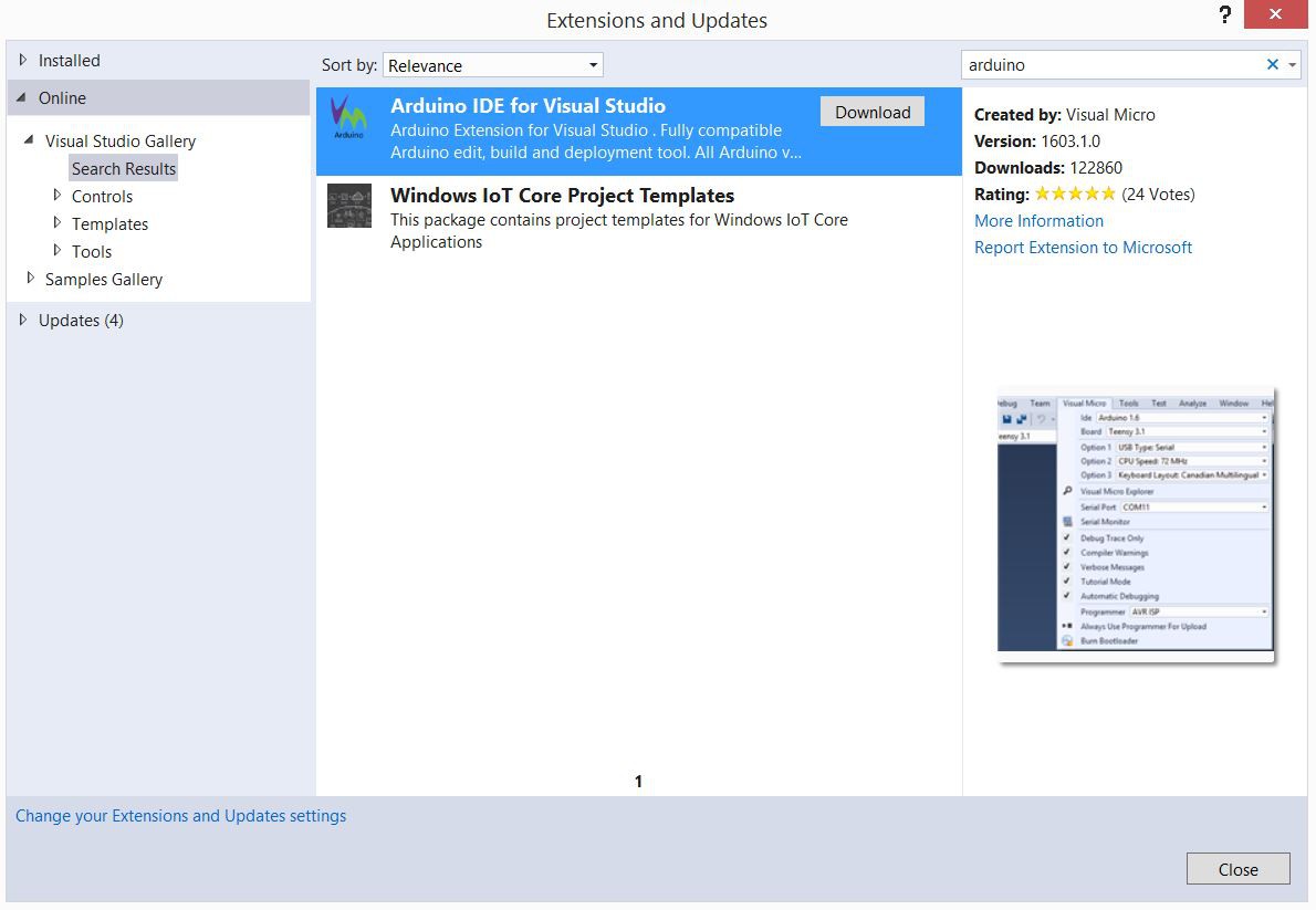
Make sure that you enable the C++ component
3. Start the Visual Studio. Go into the Tools/Extensions and Updates menu. Select the Online in the left pane. Search for Arduino
Download the Arduino IDE for Visual Studio
Install it, and restart Visual Studio as instructed.
4. After restart the Arduino configuration will appear. You should set the Arduino IDE location and add the ESP8266 Board Manager URL: http://arduino.esp8266.com/stable/package_esp8266com_index.json
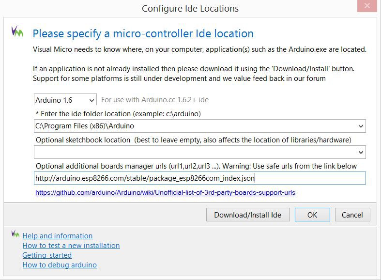
Press OK
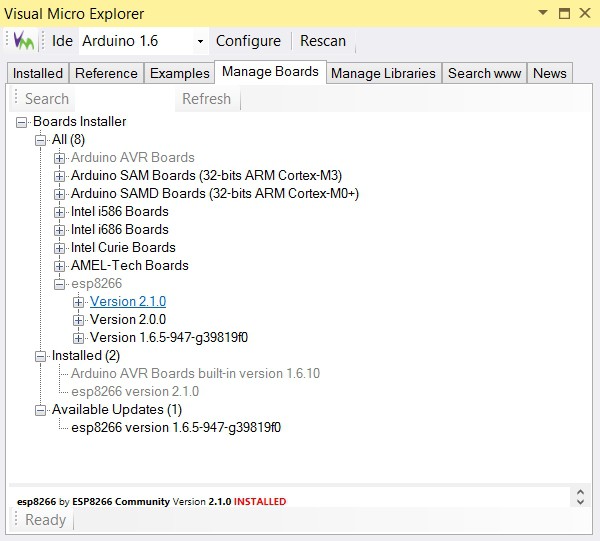
5. On the menu bar next to the Arduino board selector click on the magnifying glass icon
select the Manage Boards tab
Expand the esp8266 and click on the Version 2.1.0
On the popup dialog Click OK for the installation
And this is the point where I run into a great trouble. My machine is part of a domain, I'm running things as a regular user, means I've limited permissions (of course I'm admin on the other side, but I should specify it when I need it). It looks like the installer have a bug. Because I'm domain member and when I installed the machine at the beginning the user name I gave is the same I use in the domain. The result of this, that my profile name in the c:\Users folder is looks like this: <username>.<domainname>. This caused no problems in the past, but not here. The installer converted the dot between the name and the domain to underscore in some places and gave me an access denied error - yes because the folder in question didn't exists and I've no right to create it.
So I created the folder as admin and granted permission for me. After this the install run smoothly, but when I wanted to compile my first code, it failed. The error message wasn't too informative. After several trials, even using Process Monitor (Microsoft, formally Sysinternals tool), I was able to copy the files left in the temp folder under the underscore user folder I created, back into its place. Now it works, several hours wasted.
6. Try this out
I wanted to have a fast test, so I just created a demo project. The blink from the Visual Studio project list.
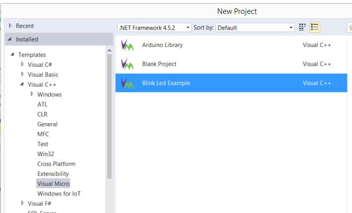
After selecting the correct board (NodeMCU v0.9 in my case) and the serial port, just uploaded the code and it started to work.
It looks like the ESP8266 environment is ready for more complicated tasks.
Make sure that you enable the C++ component
3. Start the Visual Studio. Go into the Tools/Extensions and Updates menu. Select the Online in the left pane. Search for Arduino
Download the Arduino IDE for Visual Studio
Install it, and restart Visual Studio as instructed.
4. After restart the Arduino configuration will appear. You should set the Arduino IDE location and add the ESP8266 Board Manager URL: http://arduino.esp8266.com/stable/package_esp8266com_index.json
Press OK
5. On the menu bar next to the Arduino board selector click on the magnifying glass icon
select the Manage Boards tab
Expand the esp8266 and click on the Version 2.1.0
On the popup dialog Click OK for the installation
And this is the point where I run into a great trouble. My machine is part of a domain, I'm running things as a regular user, means I've limited permissions (of course I'm admin on the other side, but I should specify it when I need it). It looks like the installer have a bug. Because I'm domain member and when I installed the machine at the beginning the user name I gave is the same I use in the domain. The result of this, that my profile name in the c:\Users folder is looks like this: <username>.<domainname>. This caused no problems in the past, but not here. The installer converted the dot between the name and the domain to underscore in some places and gave me an access denied error - yes because the folder in question didn't exists and I've no right to create it.
So I created the folder as admin and granted permission for me. After this the install run smoothly, but when I wanted to compile my first code, it failed. The error message wasn't too informative. After several trials, even using Process Monitor (Microsoft, formally Sysinternals tool), I was able to copy the files left in the temp folder under the underscore user folder I created, back into its place. Now it works, several hours wasted.
6. Try this out
I wanted to have a fast test, so I just created a demo project. The blink from the Visual Studio project list.
After selecting the correct board (NodeMCU v0.9 in my case) and the serial port, just uploaded the code and it started to work.
It looks like the ESP8266 environment is ready for more complicated tasks.
2016. április 6., szerda
AutomaTales - Remote integration
To be able to use the rolling code receiver in my OpenHAB, the first thing we need to enable the GPIO binding in the OpenHAB. There is a fairly good documentation of it in the OpenHAB wiki:
https://github.com/openhab/openhab/wiki/GPIO-Binding
I mostly done, what is in it, but some modifications were needed.
1. Install the native JNA library:
apt-get install libjna-java
2. Modify /opt/openhab/start.sh
Add
-Djna.boot.library.path=/usr/lib/jni
into the list of java command line parameters
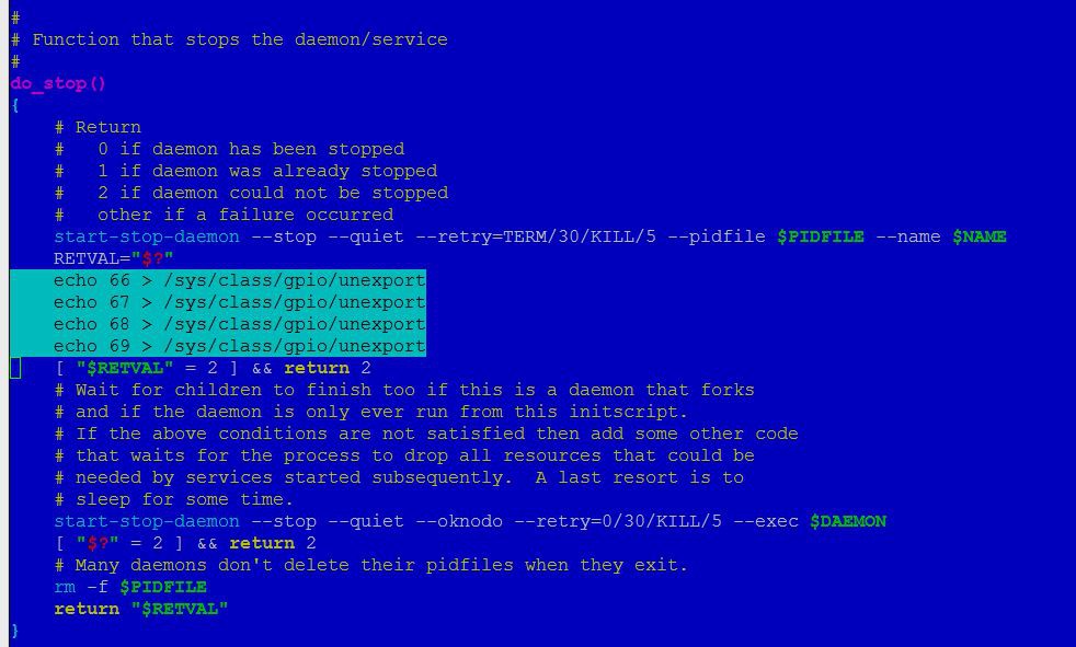
3. Modifiy the /etc/init.d/openhab
Add
-Djna.boot.library.path=/usr/lib/jni
into the DAEMON_ARGS parameters
and add the commands to unexport the gpio pins on stopping the daemon
4. From the previously downloaded distribution-1.8.1-addons.zip (part of the OpenHAB downloads) expand the following files:
org.openhab.io.gpio
org.openhab.binding.gpio
into the /opt/openhab/addons directory
5. Restart openhab:
/etc/init.d/openhab restart
Now the OpenHAB is ready to handle the GPIO. We need to make the configuration changes, to be able to use it.
6. Add the required items
The GPIO inputs can be represented by Contacts in the OpenHAB, so edit one of the files in the /opt/openhab/configurations/items directory (I already dropped the demo config from here, so I've the config of my house) and add the following:
Contact KeeLoq_Remote_A "Reamote A [MAP(en.map:%s]" (<ID of your Group>, Windows) { gpio="pin:66"}
Contact KeeLoq_Remote_B "Reamote B [MAP(en.map:%s]" (<ID of your Group>, Windows) { gpio="pin:67"}
Contact KeeLoq_Remote_C "Reamote C [MAP(en.map:%s]" (<ID of your Group>, Windows) { gpio="pin:69"}
Contact KeeLoq_Remote_D "Reamote D [MAP(en.map:%s]" (<ID of your Group>, Windows) { gpio="pin:68"}
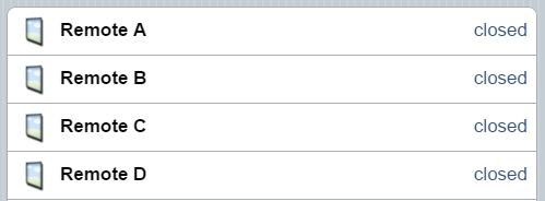
When everything is fine you should see the following after the OpenHAB reload the configuration:
https://github.com/openhab/openhab/wiki/GPIO-Binding
I mostly done, what is in it, but some modifications were needed.
1. Install the native JNA library:
apt-get install libjna-java
2. Modify /opt/openhab/start.sh
Add
-Djna.boot.library.path=/usr/lib/jni
into the list of java command line parameters
3. Modifiy the /etc/init.d/openhab
Add
-Djna.boot.library.path=/usr/lib/jni
into the DAEMON_ARGS parameters
and add the commands to unexport the gpio pins on stopping the daemon
4. From the previously downloaded distribution-1.8.1-addons.zip (part of the OpenHAB downloads) expand the following files:
org.openhab.io.gpio
org.openhab.binding.gpio
into the /opt/openhab/addons directory
5. Restart openhab:
/etc/init.d/openhab restart
Now the OpenHAB is ready to handle the GPIO. We need to make the configuration changes, to be able to use it.
6. Add the required items
The GPIO inputs can be represented by Contacts in the OpenHAB, so edit one of the files in the /opt/openhab/configurations/items directory (I already dropped the demo config from here, so I've the config of my house) and add the following:
Contact KeeLoq_Remote_A "Reamote A [MAP(en.map:%s]" (<ID of your Group>, Windows) { gpio="pin:66"}
Contact KeeLoq_Remote_B "Reamote B [MAP(en.map:%s]" (<ID of your Group>, Windows) { gpio="pin:67"}
Contact KeeLoq_Remote_C "Reamote C [MAP(en.map:%s]" (<ID of your Group>, Windows) { gpio="pin:69"}
Contact KeeLoq_Remote_D "Reamote D [MAP(en.map:%s]" (<ID of your Group>, Windows) { gpio="pin:68"}
When everything is fine you should see the following after the OpenHAB reload the configuration:
And when you push a button on the remote, the closed text change to open, and back when you release.
7. For the lighting it will not be enough
We need to keep the status of the light, as it switched on or off. So I added a Switch into the items config:
Switch Garage_Light "Garage Light" (<ID of your Group>, Lights)
This is only a regular switch, so if you want to control it from the remote you need some rules. You can add it to a rules file in the /opt/openhab/configurations/rules folder:
rule "GarageLightToggle"
when
Item KeeLoq_Remote_B changed from CLOSED to OPEN
then
if(Garage_Light.state == ON)
{
sendCommand(Garage_Light, OFF)
}
else
{
sendCommand(Garage_Light, ON)
}
end
After this, when you push the B button on the remote, it will switch the web control, on and off
This still not change the physical light. I have to create/buy some actor for this.
2016. március 30., szerda
AutomaTales - Rolling code receiver
[2016.04.16]: When I wrote this article didn't realized, that I used the old location of the cape manager slots file. Corrected.
When you sit in your car and try to enter to your garage, I know it is not fancy, but the most convenient device is the tiny remote you can hang on your keyring (something integrated into your car would be better and fancier, I may add something like this later on).
To be able to remote control the OpenHAB and the garage door/lights through it, I bought this rolling code receiver on the aliexpress:
http://www.aliexpress.com/item/RF-Rolling-Code-Decoding-Receiver-Module-2-Transmitters-DC-5V-4CH-TTL-Output-Learning-Momentary-Toggle/32295201884.html

My plan is to use it for switching the lights in the garage, control the garage doors and a few more (as it has two more buttons - exactly two) tasks.
First I put this onto a breadboard, powered up, and tried out if it works.
It was working for the first try, finding out the different channels for the buttons was easy like a child's play.
The only problem with the device, that it has 5V logic outputs and I want to connect to my BeagleBone Greens GPIO what isn't 5V safe.
I decided to use the simplest level shifter on earth possible. A resistor divider. A 39K and a 68K resistor does its job like champ, if you measure it with a multimeter.
The next part is to setup the GPIO on the BeagleBone. The OpenHAB uses the Linux GPIO Sysfs interface, what is supereasy to use (https://www.kernel.org/doc/Documentation/gpio/sysfs.txt).
First I tried to read the data from the command line. Connected one channel to the GPIO_60 (P9 pin 12) of the BBG.
On the console the following commands are needed:
3. Load it:
echo bspm_P9_12_2f > /sys/devices/bone_capemgr.?/slots
After this, the pull-up switched off. And I was able to read status of the remote.
Ok. Now it works for one channel, but what about four? I can generate four overlays, but how to combine them. I found very little information on it, until I found Adafruit's documentation:
https://learn.adafruit.com/introduction-to-the-beaglebone-black-device-tree/device-tree-overlays
Based on this, I was able to successfully combine the four generated overlays. Finally I used the P8 pins from 7 to 10.
The overlay (suf_keeloq-00A0.dts):
Compile and load:
echo suf_keeloq > /sys/devices/bone_capemgr.?/slots
echo suf_keeloq > /sys/devices/platform/bone_capemgr/slots
Now it works, but somehow it need to be loaded at boot.
To achieve this, you should add into the /boot/uEnv.txt:
NEXT: Integrating into the OpenHAB
When you sit in your car and try to enter to your garage, I know it is not fancy, but the most convenient device is the tiny remote you can hang on your keyring (something integrated into your car would be better and fancier, I may add something like this later on).
To be able to remote control the OpenHAB and the garage door/lights through it, I bought this rolling code receiver on the aliexpress:
http://www.aliexpress.com/item/RF-Rolling-Code-Decoding-Receiver-Module-2-Transmitters-DC-5V-4CH-TTL-Output-Learning-Momentary-Toggle/32295201884.html
My plan is to use it for switching the lights in the garage, control the garage doors and a few more (as it has two more buttons - exactly two) tasks.
First I put this onto a breadboard, powered up, and tried out if it works.
It was working for the first try, finding out the different channels for the buttons was easy like a child's play.
The only problem with the device, that it has 5V logic outputs and I want to connect to my BeagleBone Greens GPIO what isn't 5V safe.
I decided to use the simplest level shifter on earth possible. A resistor divider. A 39K and a 68K resistor does its job like champ, if you measure it with a multimeter.
The next part is to setup the GPIO on the BeagleBone. The OpenHAB uses the Linux GPIO Sysfs interface, what is supereasy to use (https://www.kernel.org/doc/Documentation/gpio/sysfs.txt).
First I tried to read the data from the command line. Connected one channel to the GPIO_60 (P9 pin 12) of the BBG.
On the console the following commands are needed:
echo '60' > /sys/class/gpio/export
echo 'in' > /sys/class/gpio/gpio60/direction
After this you can read the pin value by the following command:
After this you can read the pin value by the following command:
cat /sys/class/gpio/gpio60/value
The commands went well, but doesn't matter if I push the button on the remote or not, always get back a 1.
Measured the input with a multimeter. It gives 1.6V even the pin of the receiver is on 0V. This means, that the BBG input pin is pulled up.
From this point I've two choice:
1. Switch of the pull up somehow
2. Use some active circuit as level shifter instead of the resistors.
I went for the first one.
Looked around and it clearly turned out, that changing the pull-up is not part of the linux GPIO framework. Read many things and found that BBG uses Cape Manager Overlays for this task. It was sometimes there, sometimes not, but on the 4.1.x kernel what I'm using is already part of the mainline kernel.
Here are some articles about it:
https://github.com/jadonk/validation-scripts/blob/master/test-capemgr/README.md
http://www.thing-printer.com/cape-manager-is-back-baby/
http://www.valvers.com/embedded-linux/beaglebone-black/step04-gpio/
The overlay repository (you can learn from it, but not necessary for the task here):
https://github.com/RobertCNelson/bb.org-overlays
The most useful of my findings was this online tool:
http://kilobaser.com/blog/2014-07-28-beaglebone-black-devicetreeoverlay-generator
It is able to create the overlay you need.
So for switching off the pull-up on Gpio 60 above you have to do the following things:
1. Save this file into the /lib/firmware under the name bspm_p9_12_2f-00A0.dts
/*
* This is a template-generated file from BoneScript
*/
/dts-v1/;
/plugin/;
/{
compatible = "ti,beaglebone", "ti,beaglebone-black";
part_number = "BS_PINMODE_P9_12_0x2f";
exclusive-use =
"P9.12",
"gpio1_28";
fragment@0 {
target = <&am33xx_pinmux>;
__overlay__ {
bs_pinmode_P9_12_0x2f: pinmux_bs_pinmode_P9_12_0x2f {
pinctrl-single,pins = <0x078 0x2f>;
};
};
};
fragment@1 {
target = <&ocp>;
__overlay__ {
bs_pinmode_P9_12_0x2f_pinmux {
compatible = "bone-pinmux-helper";
status = "okay";
pinctrl-names = "default";
pinctrl-0 = <&bs_pinmode_P9_12_0x2f>;
};
};
};
};
2. Compile it:
dtc -O dtb -o /lib/firmware/bspm_P9_12_2f-00A0.dtbo -b 0 -@ /lib/firmware/bspm_P9_12_2f-00A0.dts
3. Load it:
echo bspm_P9_12_2f > /sys/devices/platform/bone_capemgr/slots
Ok. Now it works for one channel, but what about four? I can generate four overlays, but how to combine them. I found very little information on it, until I found Adafruit's documentation:
https://learn.adafruit.com/introduction-to-the-beaglebone-black-device-tree/device-tree-overlays
Based on this, I was able to successfully combine the four generated overlays. Finally I used the P8 pins from 7 to 10.
The overlay (suf_keeloq-00A0.dts):
/*
* SUF - 4-Channel Keyloq receiver cape
*/
/dts-v1/;
/plugin/;
/{
compatible = "ti,beaglebone", "ti,beaglebone-black";
part_number = "SUF-KEELOQ";
exclusive-use =
"P8.7",
"P8.8",
"P8.9",
"P8.10",
"mmc1_sdcd",
"gpio2_3",
"gpio2_5",
"gpio2_4";
fragment@0 {
target = <&am33xx_pinmux>;
__overlay__ {
suf_keeloq_pins: pinmux_suf_keeloq_pins {
pinctrl-single,pins = <
0x090 0x2f
0x094 0x2f
0x09c 0x2f
0x098 0x2f
>;
};
};
};
fragment@1 {
target = <&ocp>;
__overlay__ {
suf_keeloq_pinmux {
compatible = "bone-pinmux-helper";
status = "okay";
pinctrl-names = "default";
pinctrl-0 = <&suf_keeloq_pins>;
};
};
};
};
Compile and load:
dtc -O dtb -o /lib/firmware/suf_keeloq-00A0.dtbo -b 0 -@ /lib/firmware/suf_keeloq-00A0.dts
echo suf_keeloq > /sys/devices/platform/bone_capemgr/slots
To achieve this, you should add into the /boot/uEnv.txt:
cape_enable=bone_capemgr.enable_partno=suf_keeloq
NEXT: Integrating into the OpenHAB
2016. március 28., hétfő
AutomaTales - Install OpenHAB
Now here I install OpenHAB as the home automation controller, the brain of the whole system.
The OpenHAB is a java based system, so first we need an Oracle Java. To achieve this you have to add a PPA repository to the system:
BTW. I know that the sudo voodoo is absolutely necessary to keep the security. Even I'm working on my windows machine as a standard user and not admin since XP when the UAC wasn't even planed. But when I put together something on linux or windows and what I'm doing is clearly administrative task, I'm doing it as admin. So the first thing when I install several things, packages, etc. on linux I start with
sudo su
And don't bother to write sudo at beginning of every single line.
1. Add PPA repository of the Oracle Java and install it.
apt-get install software-properties-common
2. Download OpenHAB files. You will need this ones:
https://bintray.com/artifact/download/openhab/bin/distribution-1.8.1-runtime.zip
https://bintray.com/artifact/download/openhab/bin/distribution-1.8.1-addons.zip
https://bintray.com/artifact/download/openhab/bin/distribution-1.8.1-demo.zip
Actually I usually download the files on my Windows machine and transfer them to the linux via WinSCP
3. Extract the files, create configuration
mkdir /opt/openhab
unzip distribution-1.8.1-runtime.zip -d /opt/openhab/ unzip distribution-1.8.1-demo.zip -d /opt/openhab/ cp /opt/openhab/openhab_default.cfg /opt/openhab/openhab.cfg
4. As we still in sudo mode we can start the OpenHAB server to test the functionality of our system:
/opt/openhab/start.sh
After waiting for a while, we can test in a browser if it works:
http://<ip address>:8080/openhab.app?sitemap=demo
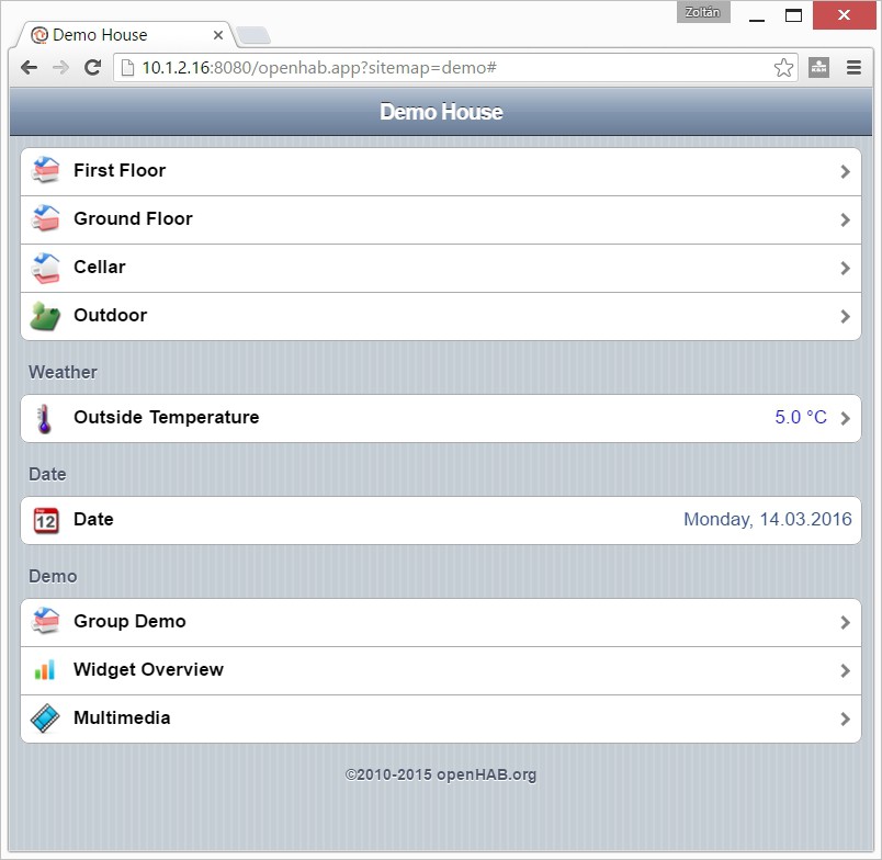
OK. Our server works, but we not yet finished. Just stop it now.
First: you may realized that I didn't created any specific user for the openhab. There is a reason why.
The Ubuntu not really designed for embedded systems. Therefore no mechanism (what I'm aware of) for regular user to access GPIO (if you know a simple method for it please don't keep inside). On the next part I want to use GPIO. Based on this I plan to run OpenHAB as root.
Second: I need a method to run OpenHAB as daemon So..
5. Download the daemon script from here:
https://github.com/openhab/openhab/wiki/Samples-Tricks#how-to-configure-openhab-to-start-automatically-on-linux
Save as openhab into the /etc/init.d folder
Configure it:
add-apt-repository ppa:webupd8team/java
apt-get update
apt-get install oracle-java8-installe
2. Download OpenHAB files. You will need this ones:
https://bintray.com/artifact/download/openhab/bin/distribution-1.8.1-runtime.zip
https://bintray.com/artifact/download/openhab/bin/distribution-1.8.1-addons.zip
https://bintray.com/artifact/download/openhab/bin/distribution-1.8.1-demo.zip
Actually I usually download the files on my Windows machine and transfer them to the linux via WinSCP
3. Extract the files, create configuration
mkdir /opt/openhab
unzip distribution-1.8.1-runtime.zip -d /opt/openhab/ unzip distribution-1.8.1-demo.zip -d /opt/openhab/ cp /opt/openhab/openhab_default.cfg /opt/openhab/openhab.cfg
4. As we still in sudo mode we can start the OpenHAB server to test the functionality of our system:
/opt/openhab/start.sh
After waiting for a while, we can test in a browser if it works:
http://<ip address>:8080/openhab.app?sitemap=demo
OK. Our server works, but we not yet finished. Just stop it now.
First: you may realized that I didn't created any specific user for the openhab. There is a reason why.
The Ubuntu not really designed for embedded systems. Therefore no mechanism (what I'm aware of) for regular user to access GPIO (if you know a simple method for it please don't keep inside). On the next part I want to use GPIO. Based on this I plan to run OpenHAB as root.
Second: I need a method to run OpenHAB as daemon So..
5. Download the daemon script from here:
https://github.com/openhab/openhab/wiki/Samples-Tricks#how-to-configure-openhab-to-start-automatically-on-linux
Save as openhab into the /etc/init.d folder
Configure it:
chmod a+x /etc/init.d/openhab
update-rc.d openhab defaults
Edit the file with your favorite editor. Most probably you only need to change the RUN_AS from openhab to root
Start it:
update-rc.d openhab defaults
Edit the file with your favorite editor. Most probably you only need to change the RUN_AS from openhab to root
Start it:
/etc/init.d/openhab start
Now you can check it again if it still works via a web browser, and you can check the /var/log/openhab.log for errors.
Now you can check it again if it still works via a web browser, and you can check the /var/log/openhab.log for errors.
2016. március 26., szombat
AutomaTales - Into my safety zone
Ok. So let start:
I'm not a linux guru. There are many favors of linux distribution, but I've just some experience with Ubuntu and Debian. In addition I usually not using any linux GUI.
So when I start a linux based project, it means to install an Ubuntu.
As I decided, this project will be based on a Beaglebone Green. Let start to install a 14.04 LTS to it.
The basic information reside here: http://elinux.org/BeagleBoardUbuntu
1. You need to download the image from here: https://rcn-ee.com/rootfs/2016-02-11/flasher/BBB-eMMC-flasher-ubuntu-14.04.3-console-armhf-2016-02-11-2gb.img.xz
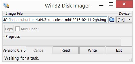
(today the 16.04 image already exists, but I stick to the older as it seems more stable), download the image writing tool (Win32DiskImager): https://sourceforge.net/projects/win32diskimager/files/latest/download
And you need an empty minimum 2GB uSD card.
2. Expand the image to a folder in you machine. For example the 7-Zip will do it. Install the Win32DiskImager.
3. Write the image to a uSD card with the Win32DiskImager
4. When the writing is finished, insert the uSD card into the Beaglebone. Press and hold the boot select button (the one close to the uSD slot) while powering up the board. After short booting sequence you will see the "knight rider pattern" on the LEDs. Wait until it finish and the leds turn on.
5. Connect the board to the ethernet network. If you can figure out the address get by DHCP the steps from 6-8 are optional. Just reboot the board by power cycling it.
6. Install the PC driver for the board (if you have a BeagleBone Green, this is absolutelly necessary as you don't have HDMI connector to connect monitor). The windows driver can be downloaded from here:
64 bit: http://beagleboard.org/static/beaglebone/latest/Drivers/Windows/BONE_D64.exe
32 bit: http://beagleboard.org/static/beaglebone/latest/Drivers/Windows/BONE_DRV.exe
This is NOT a serial driver as you expect, but a virtual ethernet driver. You will need an SSH terminal to connect to Beaglebone.
7. Connect the Beaglebone to your PC. If it is was connected already, just cycle the power on it with removing and reconnecting the USB cable, when you disconnect the cable you can remove the uSD card, as you don't need it anymore.
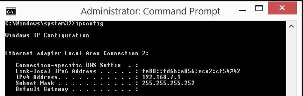
8. If you run ipconfig on your machine a new ethernet interface will appear:
I'm not a linux guru. There are many favors of linux distribution, but I've just some experience with Ubuntu and Debian. In addition I usually not using any linux GUI.
So when I start a linux based project, it means to install an Ubuntu.
As I decided, this project will be based on a Beaglebone Green. Let start to install a 14.04 LTS to it.
The basic information reside here: http://elinux.org/BeagleBoardUbuntu
1. You need to download the image from here: https://rcn-ee.com/rootfs/2016-02-11/flasher/BBB-eMMC-flasher-ubuntu-14.04.3-console-armhf-2016-02-11-2gb.img.xz
(today the 16.04 image already exists, but I stick to the older as it seems more stable), download the image writing tool (Win32DiskImager): https://sourceforge.net/projects/win32diskimager/files/latest/download
And you need an empty minimum 2GB uSD card.
2. Expand the image to a folder in you machine. For example the 7-Zip will do it. Install the Win32DiskImager.
3. Write the image to a uSD card with the Win32DiskImager
4. When the writing is finished, insert the uSD card into the Beaglebone. Press and hold the boot select button (the one close to the uSD slot) while powering up the board. After short booting sequence you will see the "knight rider pattern" on the LEDs. Wait until it finish and the leds turn on.
5. Connect the board to the ethernet network. If you can figure out the address get by DHCP the steps from 6-8 are optional. Just reboot the board by power cycling it.
6. Install the PC driver for the board (if you have a BeagleBone Green, this is absolutelly necessary as you don't have HDMI connector to connect monitor). The windows driver can be downloaded from here:
64 bit: http://beagleboard.org/static/beaglebone/latest/Drivers/Windows/BONE_D64.exe
32 bit: http://beagleboard.org/static/beaglebone/latest/Drivers/Windows/BONE_DRV.exe
This is NOT a serial driver as you expect, but a virtual ethernet driver. You will need an SSH terminal to connect to Beaglebone.
7. Connect the Beaglebone to your PC. If it is was connected already, just cycle the power on it with removing and reconnecting the USB cable, when you disconnect the cable you can remove the uSD card, as you don't need it anymore.
8. If you run ipconfig on your machine a new ethernet interface will appear:
You'll get 192.168.7.1 as a new interface on your machine, the Beaglebone will appear on the 192.168.7.2. You can connect to it with an SSH terminal like PuTTY
9. If you didn't used the USB/Ethernet to log in, just login via the DHCP provided IP address. If you need static IP address edit the /etc/network/interfaces file and setup the address.
10. If you check the DNS settings of the system it is probably not working. Just by editing the /etc/resolv.conf will not resolve the problem, as it gets overwriten on the next reboot.
Edit the /etc/resolvconf/interface-order file and put eth* to the first on the list. This will give you the correct DNS settings.
11. Reboot the board.
12. Install the updates with:
apt-get update
apt-get upgrade
2016. március 25., péntek
AutomaTales - Why?
I'm planning this since we bought our new house back in 2009. I wanted to have some automation right from the beginning. I've a friend who deeply involved in KNX systems. He said, that the cost would be around 10% of the house. I wasn't willing to pay such amount of money at that time, so I just drop the idea.
Of course some automation appeared here and there, but no integration between them.
I had a few attempt to the automation, but it didn't went further.
Just to collect them:
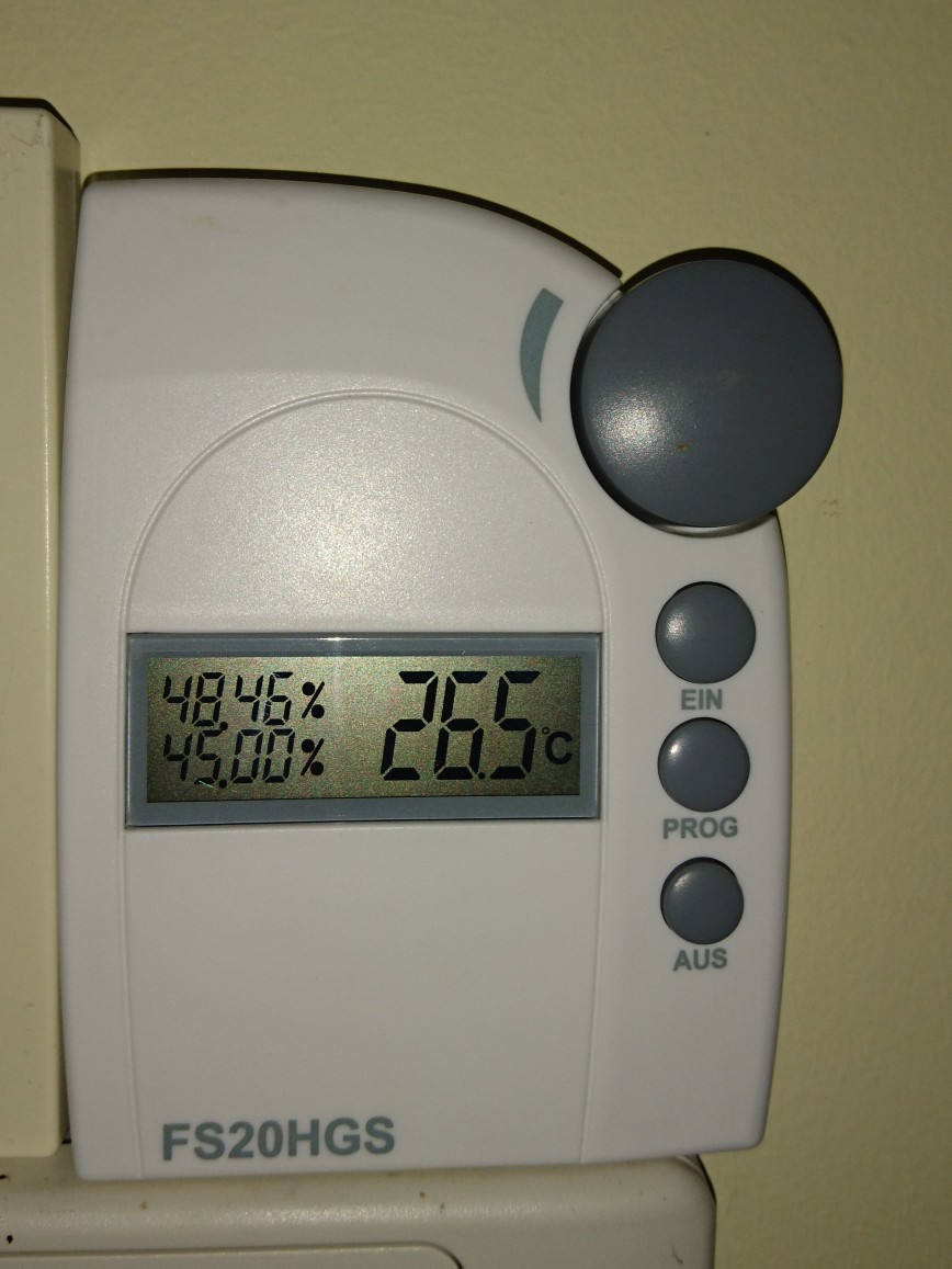
- Bought and installed few Conrad FHT80B thermostats and connecting valves. These are working today as "islands" in the house.
- Bought and installed a humidity sensor and switch (part of the Conrad FS20 system) for controlling my dehumidifier (the integrated control was a heap of crap)
- Bought the computer interface and the code monitor for the FS20 system. The interface is still in a box. The code monitor (or call it debuger) was used a few times
- Bought the CUL v3.2 for controlling the FS20 but kept in one of my parts boxes until now.

- Designed and built a few thermometers, what was planned to be a base project for a future thermostat project what never happened.
As you see almost nothing happened until now.
Why now?
As I'm progressing with my electronics projects, it got some attention from my wife. Attention means task here.
In our garage you can't see anything if you don't switch on the light, but you can't switch it of after you get into the car. The result: if I'm lazy (sometimes I'm) the light left open.
The task: resolve this issue.
It would be a simple solution, to change the switch to a momentary button and add a timer, but....
I want to create a home automation system. This is a good starting point. So rather a simple solution, why not start to build a big one? :-)
2016. február 8., hétfő
Isolation transformer
The reason behind, I started to work on (my still unfinished) CNC Motor driver project is connected to two accidents:

When I exchanged the spindle motor of the CNC from 230W to 400W and the power supply from the unknown underpowered linear crap to a 600W switching mode supply, the later one just blow because of the missing protection diode (my fault)
When I started to repair the above supply, I made the second mistake. I forgot that all mains powered oscilloscope is ground referenced. Second blow, and the repairable supply completely destroyed.
So Is started the CNC motor driver project and on the side I figured out that I definitely need in isolation transformer to avoid such kind of accidents.
I ordered, bought several parts for the transformer - a toroid isolation transformer, an enclosure, switches, connectors, and a nice multifunction panel meter, what able to measure volts, amps, watts, voltampers, and power factor.
All of the parts was lying around in my workshop, as I didn't want to cut, drill the necessary holes to the front and back panel of the enclosure, by hand. I waited to finish the CNC, to do this job.
A few weeks ago I was thinking of testing some power supplies for the home automation project. As I built an electronic load for this, the isolation transformer also appeared as a required tool.
Today I'm in a better situation. May CNC still doesn't work, but the 3D printer does. So what if I just replace the aluminum front and back with plastic, as I did in the electronic load project.
I did it.
Here is the result:
2016. február 1., hétfő
Load
The next big thing I want to work on is my home automation project (but just after I finished some of my actually running thing, like the build siren).
There is a well established central management - OpenHAB - available. Controlling it from whatever you want, also not a problem (Web, iOS, Android applications are available).
Building remote sensors, actuators nowadays is easy. Plenty of it can be found on the internet based on cheap IoT platforms like ESP8266 modules. Connecting different kind of sensors, relays, SSRs, just a piece of cake. Powering this remote thing is much trickier, even the mains line is available. The primary goal of my project to save energy. Consuming much power to measure some device power consumption is really bad idea.
So before I begin the project I'd like to find the most efficient way of powering mains connected sensors (remote sensors without mains connection is a different question - battery powering, energy harvesting, etc. - and I want to deal with it later time). There is a handful of way to design a power supply for this. The requirements:
- As efficient as possible
- Able to provide 200-250mA at 3.3V (maybe 5V) (Power consumption of the ESP8266: http://bbs.espressif.com/viewtopic.php?t=133)
- As cost effective as it can be (I want to build large amount of devices, so the cost matters)
- The electrical isolation is clearly not required. The efficiency is much more relevant
Ok, I don't want to go through all of the possible solution (Resistive, Capacitive, Linear, Isolated and non-isolated switcher, etc.) now. I want to buy/build some, and test them.
For comparing the performance of the power supply variants I desperately need a constant current DC load.
First I was looking around the forums, markets, to find a solution. I was looking for two kind of devices:
1. A cheap one, what can be used as low current load, and not heart to put it aside when I need a pro thing
2. A professional one, what can be used later on, for other projects.
In the first category I found none. Looked around the ebay, aliexpress, tindie, but all of the things I seen there was not suitable for the task or not fall into the first category.
In the second category I found the Maynuo M971x series:

There are quite good reviews about it on the net, but my actual needs doesn't justify $400-600 spending (depending on model it will became the amount together with shipment and customs fees).
So my decision is to build one.
I said before, that I didn't find a suitable cheap one. It is true for the already built models, but on the other hand I found the device what I can build upon. The re:load 2 from Arachnid Labs. http://www.arachnidlabs.com/blog/2013/02/05/introducing-re-load/
Why I not just bought it?
Because it was designed with different requirements. The low current capability and the precision control was not a requirement, but the protection and the self powered operation was.
My design is:
- Powered from independent supply (this time I'll use an AC wall adapter - leftover from my ancient Draytek routers)
- Internal 12V DC supply (higher voltage is useful from many points: OpAmp, selection, optional cooling fan, drive non logic level MOSFET, etc.)
- Changed the current feedback resistor to a much higher value. This decrease the noise and the OpAmp offset problems. On the other side I get 2V voltage drop at 2A load, and I don't want to use this for anything bellow 3.3V.
- Changed the MOSFET to a normal cheap n-channel one (to a type I found in my parts box)
- Added the capability to compensate the OpAmps offset voltage (0.6V negative supply and some trimmers)
- Added range switching capability (0-200mA, 0-2A)
- Changed the normal potentiometer to a 10 turn one
Here is the final schematic:

Built on BreadBoard:

The PCB design:

I choose a metal box for the equipment, but I didn't want to drill several holes to the front panel (the back is a different story it has only one hole what isn't a problem), so designed a 3D printed one.
Here is the result. The equipment fully assembled (without the top), measured, working:

2016. január 19., kedd
Motherboard repair
I had a home grew storage server based on Nexenta. It was working for a few years. Unfortunately it wasn't stable. The storage part was rock solid, but the web interface died frequently. In addition I had problems with the boot SSDs.
A few weeks ago finally I migrated everything off it and disassembled the machine. It come out, what I thought is a software problem, maybe a hardware issue:

Two of the same size/type capacitors are dead on the motherboard. As I realized no known (at least to me) markings on the cap, I thought that Intel played incorrectly and used some cheap shitty caps.
Desoldered them, looked around the net, and found out, these are United Chemicon Low ESR caps, so good quality. Maybe this series has some manufacturing issue. Out of the several ones on the board just the 3300uF/6.3V ones died:

8.8uF and 13.4uF in the place of 3300uF not really looks like enough. :-D
2016. január 18., hétfő
MobileVise
For my soldering work I almost exclusively using the StickVise to keep the boards, connectors, etc. in its place on my desk.

As I'm not working in the electronics industry in my daily work, I don't have it in the office just at home. It happened that I was need to solder some audio cable there. Without the StickVise it was a horror.

As I'm not working in the electronics industry in my daily work, I don't have it in the office just at home. It happened that I was need to solder some audio cable there. Without the StickVise it was a horror.
During the weekend, I was thinking. What would be the solution. I deffinetelly don't wan to carry a StickVise in my bag. I need something like it, but something portable. Than I figured out the solution and the MobileVise born.
After a failed attempt (one of the screw holding clips broke almost imediatelly, because it was too tight, etc.), here is the working one.
The design:

Closed:

Open:

Assembled:

In action:

The movie:
The design:

Closed:

Open:

Assembled:

In action:

The movie:
Feliratkozás:
Bejegyzések (Atom)