A következő címkéjű bejegyzések mutatása: metrology. Összes bejegyzés megjelenítése

2023. szeptember 5., kedd

Fluke 787 "Repair"

Big thank you for DuraLeak.

"i purchased this at an estate sale.  i don't know if it works or how to turn it on.  but as it is right now i have pushed every button and nothing comes on the screen.  so because of that i am selling it for parts or repair."


Perfectly working Fluke 787 Processmeter for $143 delivered to Hungary


I need some future tests, but looks ok, for the first sight.

2023. május 8., hétfő

Analog Multimeter 2.

Since the first post on my analog multimeter happened a few things.

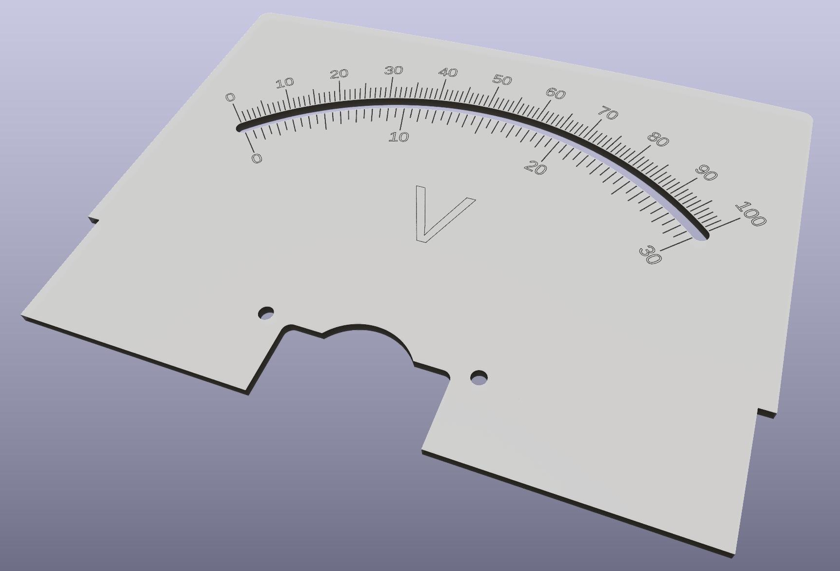
I was thinking about the scale plate. If I order it as a PCB, why not to add some useful electronics to it. And I did. Adding a few LEDs will give a perfect backlight for the meter.

Also, I figured out, what to add to the back side. I've a few from this meter in the box with center zero configuration, so I added the same layout (with the LEDs) to the back side with center zero scale. Removed the "V" designator from the original design to add some versatility.


The back cover, with the mirror (3D printed insert + mirror foil) assembled:


Let there be light:


The assembled panel meter (no, I will not keep this scratchy plexi cover in the final instrument):


On the side, I started to work on the electronics. As it still far from ready, a few things are already settled. First of all the power supply voltages - Yes, you can tell it is too early, without the final design, but by my opinion, is a right time to try out some things.

What I already know about the analog section that I need a symmetrical, very low noise design, with the minimum achievable offset voltage - It is my assumption that the supply voltage is not really mater in a certain range, but the positive and the negative rail should match as much as possible.

So I "designed" an analog power supply. This first version is just to prove my concept, definitely not the final one. It will provide +-5V, roughly 1A. It is based on Walt Jung and Jan Didden's work called "SuperRegulator". Actually, I changed the reference to an MCP1502-25 from Microchip, changed the level shifting zener to LEDs (according to Walt Jung, it generate noise), and the negative side is not a separate regulator, but a tracking one. Also the Op Amps supply will be symmetric.

The design now is SMT except the power elements (two power transistors and two pre-regulators) also used a DIP socket for the Op Amp, to be able to try out different ones. My plan is OPA2180, but we will see, what is the best option.


I also designed the board for it:


Roughly a week ago I got a message from PCBWay marketing, that they recognize my work, and intend to sponsor my efforts with the PCB manufacturing.


This is an excellent news for me. This board is ordered from them. I eagerly waiting to arrive, and be able to review and also build this design. I'm looking forward to work with you guys.

My planned design for this meter is full of Op Amps. There is an Op Amp competition running at Hackaday currently: https://hackaday.io/contest/190312-op-amp-challenge.
I'm thinking about to enter with the part of this instrument.
Actually a circuit is "itching" in me for a while. This is a precision rectifier. Yes, you can tell, this is a well known, commonly used thing, but ...
Yes, that "but" is always there. I seen something as a patent entry from Microsoft (yes, this is funny, why Microsoft is trying to get a patent on an analog circuit), what, as it looks like not accepted.
This is what I feel a really good solution. I don't found drawbacks, but I'm really not qualified to judge this.
So, I started to design something based on that. Currently it is just a simulation, not using real components, it is just for functional proof.

The circuit:


It is based on an inverting and a non-inverting imput Op Amp (keeping constant input impedance, and creating inverted output also), a comparator, an analog switch and an output buffer.
Here is the produced waveform:


Don't forget, right know it is only theoretical, and low frequency. In the analog multimeter project I not even planning to use it for rectification, rather for automated polarity switching.
Next, I'll design the real circuit and PCB for not just test the functionality, but also the performance of it.
This is all for today. I'll continue (hopefully soon)

2023. március 20., hétfő

New Arrival 10. - Additions to my lab

There are many other things arrived since the last "new arrival" post, but today, I'd like to focus on the additions to my lab.

Agilent 53131A

Actually a few years ago I bought a 53181A Frequency Counter. Actually one of my former projects required a two channel counter, so it was itching in me, to get the bigger one.

For surprise my old 53181A had the high stability oven option. So now, I moved the OCXO reference to the new unit. I'll sell the 53181A finally (no, don't ask for the price, I've the buyer for it).

I finished the project were I think before, I need the analog multimeter, during the weekend - without it. Before that I scored this nice Hioki FET multimeter.


I don't know, if or when will I need it, but for ~$40 is nice addition to my lab (actually building some bench unit is still in my focus)

I still have one half junk PM3082 oscilloscope lying around. I didn't give up to repair it. There is no picture on the CRT. My suspect is the high voltage supply. Playing with the 16500V rail is not a child play.

I scored this for nuts, to achive the task (when I have time for it):


Fluke 80K-40 probe in carrying case. Good for 40kV.

Two additional equipment. Those are not yet arrived. Those are somewhere at the currier services

Bruster Digistant 6405

Yes, I have already a similar unit, but for GBP60, I can't leave it there.


Boonton 8201 Modulation Analyzer


No, I will not become an RF guy. Actually I've four Panasonic/Leaver VP-8193 units. I want to test, repair them (and finally sell three of it).
I read through the service manual. I have most of the required or similar test equipment mentioned in the manual (Audio Analyzer, Oscilloscope, Low frequency spectrum analyzer, multimeters, etc.)
The only missing piece was the Modulation Analyzer/Measuring Receiver. The manual mention HP 8901A/B or 8902A. Those units are going for insane price on the eBay.
I was thinking to try to simulate the function with my HackRF SDR, but I think the result will be questionable, and probably need some programming, what is time.
I was so fortunate to score this unit for the third of the cheapest HP 8901A. I think this one has the same, or better function, and optically looks much better, than any HP unit I seen online.

2023. március 8., szerda

Analog Multimeter 1.

I restarted to work with electronics around 15 years ago.

At the beginning I decided, not to use analog meters (except on audio amplifiers) anymore. Those are not precise, outdated, etc.

But the things are changing.

I started to working on a project, what done some weird things. I guess, with changing the load, the power voltage is dropping and disrupting the input measurement.

This is something, I will never see on a regular digital multimeter. I either can use some higher speed data acquisition and record the result on a graph, or use an analog multimeter and see the needle movement.

Actually I don't have none of the methods actively setup at my lab.

I decided to go to the easier way, and get an analog multimeter working. 

I still have an old Russian meter from the soviet era, inherited from my grandfather (he were the person teaching me electronics, when I was six). This meter was lying on the ceiling, as I didn't use it.

This meter wasn't switch on let say 30+ years.

This can be seen on the batteries left in it:


At least, those doesn't cause to much damage. Just some minor corrosion.


Anyway. Those meters only use batteries for resistance measurement. For this, I'll definitely will use my digital meters. So no batteries going back to the case.
Opened it. Actually it had the original factory seal on one of the screws. It was never opened before.


It is in perfect condition internally.
Tested. It is spot on. So I'll keep it for my measurements, where analog has advantages.
This could be the end of the story. But as usual, the little devil in my mind started to chase something.
I like much more the bench instruments than the handheld ones.
Looked around on the eBay. But didn't find any subject with reasonable price and condition.
What would be the result, if I design something, with the current component possibilities.
I have quite a few Ganz 101DA-2 panel meter. I bought a few as new, a few others on a ham market.
Based on those meters, I may can produce something interesting.
First, I started to work with one of the panel meters.
These things are by design has 100uA full range. The ones I bought has internal shunts to 5 or 20mA. First I wanted to remove those.


Last time I was playing with those units, I was a bit rude. Directly measured the resistance of the coil, what is definitely not a good idea (https://pakahuszar.blogspot.com/2022/09/analog-meter-resistor-sizing.html).
This time I was much more careful.
Used my Digistant voltage standard as source (it is not calibrated, and a bit off, but it is perfect for a very low voltage source), a current and a voltage meter.


So the result for the full scale is 95uA and 22.22mV. This means two things to me:
The coil resistance is ~234 ohm, and I can drive meter to full scale with let say 25mV. So I can play with these values.
With a good low noise FET input opamp, I may can go down to uV range while keeping high input impedance (thinking about 100Mohm).
We will see the results.
As you see the original scale plate is white, with just the start and the end marks. It is made from 0.9mm aluminum. I need a scale, but I have no equipment to make it from aluminum and paint is accordingly.
In addition, it would be nice to have a mirror scale (why not, if you can).
The original case, even have place for the mirror


I was thinking to find a place, where somebody can cut the proper mirror to me with waterjet. Thinking it further, I decided, to design the mirror size, print it in 3D and use a self adhesive mirror foil on it.


Next is the scale itself. I was thinking, how can I create the scale. First printing on paper and laminating it was my idea. But this is not the best for the mirror scale, as the cutout would not be easily achievable.
Then came the idea. What if I design it in KiCAD and send it to a board house for manufacturing.
So the design born. The scale was designed in OpenSCAD, exported to DXF and used by KiCAD.
Here is the result:


As the board house create minimum 5 pcs, I'd like to figure out, what design to put to the other side. Then I'll send to manufacturing.

This is for now. I'll continue, as my build advance...

2020. szeptember 9., szerda

Instrument Control 1. - The Beginning

 Convergence.

This is the word what pop into my mind when I think about this project.

I feel this is the point where my lab building, instrument collection, instrument/interface building and measurement efforts connected together, giving me some higher level capabilities, than the things what I have on hand.

Where this is started?

I was building audio equipment in my childhood. Later when I restarted this hobby, was the plan, to continue to work audio electronics. I was lack of test equipment (had just a dying DMM). I wanted to build instead of buying. This lead me to the digital electronics.

Later I bought lots of equipment. At a point of time, I bought a HP 8903B Audio Analyzer, to be able to draw various graphs on amplifier performance. But the problem is, connecting an XY recorder is an outdated solution. For connecting to a computer, you need an interface. I wasn't happy with the readily available GP-IB interfaces, so my GP-IB interface is born.

Later, I was looking into the available controller software for the HP 8903B, and didn't like it. In addition, I wanted to connect/control my other instrument to a PC, having more ideas than just controlling the audo analyzer. So after a few control experiment, my "Virtual Instrument" project is born.

After two years, with many struggling, restarting and redesign, it looks like the system started to work.

The concept:

I wanted to create something flexible, while it able to use without programming skills. I wanted something can be used for serious measurements, can be used with many of the instruments I have. Compatible with several communication interface types. The whole system need to be use plugins for the future development.

I created a few object types  

Controller:

Something run the show. Starting the measurement series, even providing some base data for the instruments. Currently I implemented these:

- Continuous controller: Just runs the measurements one after the other. This is the usual work scheme most of the instruments, like multimeters.

- Single shot controller: Just run one measurement, then stops

- Variable controller: Can be setup for a series of measurements. It provide a linear or logarithmic dataset. It is originally created with the HP8903 in my mind. In the first trials I used it as a logarithmic frequency source for the integrated sine wave generator

Instrument:

Some device (typically hardware), can measure something. Can consume measurement results from the previous instruments (or controller) in the chain and/or provide measurement results for the next object.

Currently two type of instruments created: HP8903 Audio Analyzer, HP3478A 5,5 digit DMM

The instruments always working in single shot triggering mode. The reason: The controllers above are running the show and not the instrument's internal controller.

Filter:

It is originally designed for filtering, running maths, converting the results. During the development I realized, that similar functions are needed between the instruments also. So I realized that keeping filter plugins separately from the instruments has no added value.

I'll drop the filter functionality and create the filters as instruments.

Target:

Something can display or save the measured results. Currently two target available:

- Digital Display: can display the currently measured data, also provide min, max and average displays, with variable number of digits displayed

- Chart Display: Capable of displaying the measured data in a chart, using multiple series of data, using linear or logarithmic axes (this is not completely ready)

Connections:

Not part of the measurement chain. It is used by the instruments as communication interface. Currently available:

- AvrGPIB - My own GPIB board (on the development I wrote a few articles)

- IVI VISA - The standard instrument interface. I tried it with the Keysight stack and a Keysight USB/GPIB interface. Actually it was quite unstable, so future development is needed

- Serial - It is implemented and not. Actually it is used by the AvrGPIB, but I never tested directly, so it can have problems

So, this is what I have right now. I tested with the HP 3478A:

And later with the HP 8903B:

It is just AC Level measurement, the input directly connected to the output with 20-20000Hz sweep, 1V AC. Actually you can see some error:

Later with some modifications on the graph (still not finalized):

You can see around 2% error. So the instrument need some repair (at least replace of the filter caps).

So I intend to continue the development, adding support for other instruments and I have many improvement idea.

The code is written in C#.Net with Visual Studio 2019. The repository is located here: 

https://gitlab.com/suf/suf-electronics-VirtualInstrument

Anybody like this project, have spare time, some programming knowledge, and willing to help in the development effort, wellcome.


2020. április 14., kedd

GP-IB 4.

Nine month. Today exactly nine month ago written last about my GP-IB adapter (http://pakahuszar.blogspot.com/2019/07/gp-ib-3.html). Its been a hard delivery.
I'm announcing proudly the birth of the working GP-IB interface software. It still need to learn and grow. Things are missing from its skills like device mode and USBTMC capability.
Both the father:


The mother:


And the child:
https://gitlab.com/suf/suf-electronics-gpib

In good shape:


And waiting for a long and prosper life.

2020. április 9., csütörtök

HP 3488A

This will be a long association chain. Just follow!
It is started with a picture on facebook about a Kenwood analog two channel AC voltmeter. It can be nicely used to check stereo audio equipment channel differences. I love the concept, but still I'm not an analog meter guy.
I was thinking. What if I pickup one of my digital bench meters and develop some desktop software around my own (still in development) GP-IB USB adapter, and add an uncontrolled MCU based channel switch. Uhh, this sound ugly, in addition, this is not the post where I will explain it. Just get it, I'm developing it, and publishing soon.
So go back: I chosen one of my HP 3478A 5.5 digit multimeter for this. And here come a few things.
  • I need a switch for the project
  • The display of the 3478A is a heap of crap without backlight
  • I don't want to kill the original display on those unit, so get something similar, cheaper.

As usual I was looking around the eBay. And look what I found. Two HP 3488A. those are loaded with cards (usually you can find it empty), for €102 delivered. So I bought it immediately.
It is a good practice for the display modifications, if they work (the seller didn't guarantied it), can be used as a switch for the project above, and also for other purposes. Also, it nicely fit into my test equipment collection.
So here they are:


First of all, I removed all of the cards, cleaned the units (get rid of all of the stickers, dirt)
Let see the inventory:

  • Two HP3488A units. One of it miss its power button. No stands.
  • Two 44471A General Purpose relay cards. One of it even has the connector block, the other don't
  • Two 44470A Matrix relay cards. Both of them with connector block, just from one of the blocks the plastic insert was missing

One misterious, HP branded, and hacked - some (not even nice) modifications are made by one of the previous owners.
This is the mysterious card, I would appreciate, if somebody can give me any info on it:


After a bit cleaning, I tried out the units. for the first smoke test, both looks like working, the self tests are succeeding, I can hear the relay click from console, and from remote GPIB commands.
As you know, I'm in the 3D design, and printing for a while.
Here I needed two missing plastic parts. One for the power switch replacement


And one for the connection block insert.
I designed both, in my regular OpenSCAD:


 Here they are printed:


Left is the original, right is the printed:


Now, the power button in its place:


Project of getting in shape the HP 3488A units now completed.

2020. április 1., szerda

2kW Bench Power Supply 2.

Please don't look for the first part under the title above! It was published as Few stories ...
It took a while to go further with this project.
I built and tested the my delay circuit mentioned here.


Works as expected.
Done all of the cabling, mechanical work, needed for the assembly.


I was choosing a C20 connector instead of the regular C14. The two power supplies can consume maximum 3kW, so I felt that a bigger connector is needed.
After almost of a year skip, I restarted my 3D printer. So I created a 3D printed back panel:


I made a short video shot to show how the delayed startup of the two supplies works:


So, this unit is working now. The only thing is missing, the computer control.
The two units originally has two separate optically isolated USB to Serial units. I wanted to solve this with one USB port. So, I ordered a dual channel FTDI module, what unfortunately not yet arrived.
The USB port already assembled to the back, it just waits for the module and an optoisolator board design from me. This will be the second phase of this project.