I'm kind of maniac, if it comes to the VFD displays. I've several instruments in my lab with VFD.
Even I collected many various versions with the thought, once I'll build something from it. Actually my first acquisitions were VFD modules, what already have all of the power supplies, so I not need to know, how to power, how to drive them.
On the other side, I always wanted to know, how VFD displays are working, how they need to be driven.
This story begins 8 month ago, just the half written article was put asside.
Then I seen this nice bare VFD so cheep, I couldn't resist. Bought them and my learning journey begins.
Now, I already know, it works like the vacuum tube.
It needs some heating voltage for the cathode, need anode voltage, and it have a grid to control the electron flow from the cathode to the anode.
In addition it has direct heating, so the cathode and the heating connected together (here it called filament supply). It is somewhere around 2.5V and recommended to use AC voltage (few 10th of kHz) to achieve even light distribution from one end to the other (the heater strings are connected to the two end of the VFD tube). For the anode/grid you need a voltage around 30V (it can change from tube to tube). With this one I was fortunate to figure out the original equipment this VFD was installed, got a service manual. It looks like it needed 32V.
On the side of the power supplies I need some IC, designed for driving VFD.
I choose PT6324 from Princeton Technology.
It is cheap and easily available from the eBay. Also it able to drive all of the segments of this display.
There is not uncommon, but for first sight it could be felt weird, that the IC need high negative supply voltage instead of positive. So in my case it need 5V logic supply, -27V VFD supply and a 2.5V AC filament supply superimposed to the -27V supply.
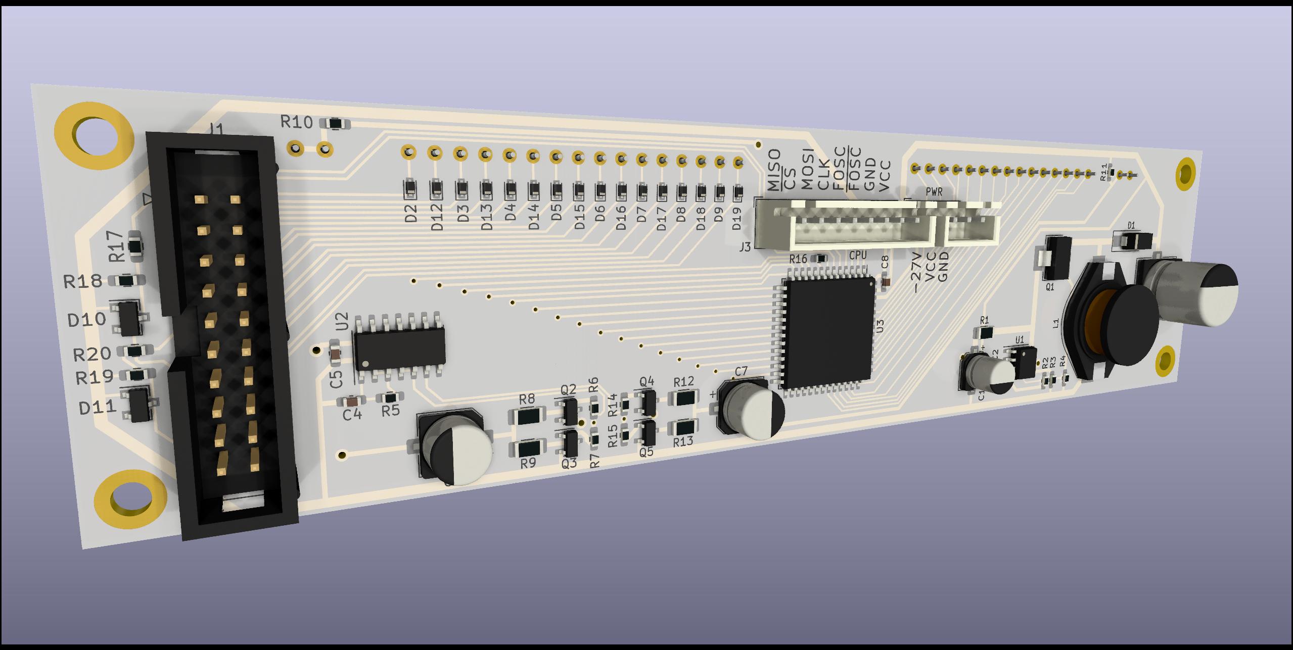
I actually designed the whole module...
...but I had a feeling, I may did something wrong, so I broke the design into pieces, ordered the power supply boards separately, so I can test it, before send the whole module to manufacturing.
The git repo of the design is here:
https://gitlab.com/suf/suf-electronics-vfd-futaba-15mt67gnk
To be continue..


Nincsenek megjegyzések:
Megjegyzés küldése