A következő címkéjű bejegyzések mutatása: VFD. Összes bejegyzés megjelenítése

2023. május 10., szerda

VFD Mania 3. - Reverse engineering, filament supply

In the last few years I collected many VFD tubes. In the last weeks, a bit cleaned it up, unsoldered a few to have just bare tubes.


This is not all, but most of it what I currently have.
I wanted to make a catalog for myself with the pinouts. On the internet there is no common source of these. No datasheets, etc.
So the reverse engineering is required. For this I built a small, simple device (it took less than an hour from the idea).
For testing I need a 2.5V as a filament supply (may not the ideal solution, but good enough for testing), and something (12V good enough), for the anode and gate.
So, I built this:

The two blue banana can be connected to the filament pins, the two red sockets for the gate and anode. With this I can quickly find the segments.
Currently documenting it to a simple Excel sheet, but looking for a better solution, to able to publish it.
Finally took the time to test the previously designed/built filament supply.


It started to work immediately, but...
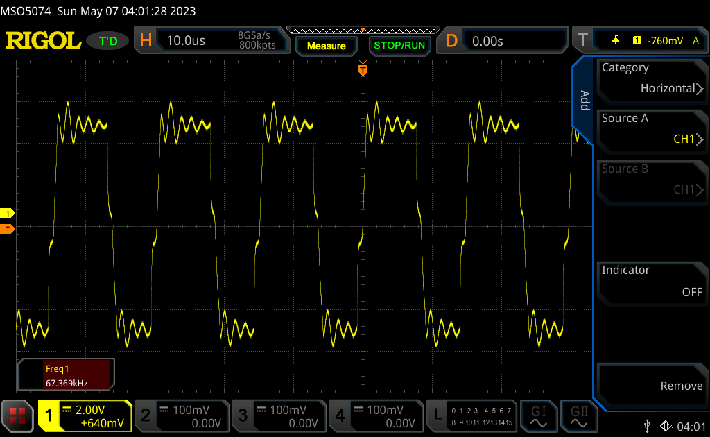

The waveform is horrible.
Superposed to the -27V supply is not much better:


My first hint was instability at the last inverter (but it was highly unlikely). Testing, the previous circuit state generated this:


I got a hint from a group (I would try it myself anyway), to check the supply voltage.
It looks like, the 20cm cable I used has too much resistance.
Adding a 1000uF capacitor to the input voltage of the module produced this:


Still has some overshoot, but I think, I'll be able to handle this at the final design.
Next, I'll order the complete PCB for the Futaba 15MT67GNK and the Princeton controller IC.

2023. február 26., vasárnap

VFD Mania 2. - Inverting boost converter

For the -27V supply I mentioned in the first part of the series (https://pakahuszar.blogspot.com/2023/02/vfd-mania-1-preface.html), I wanted to have something cheap, and from easily available parts.
Yes I know, that the MC34063 is old, not to effective, but still widely available, has calculator, tons of circuit configuration in the datasheet, and extremely cheap.
As I wanted to create -27V from the 5V supply (I want to run the module on the way, to have only a single supply input), I decided to have an additional external transistor, as even with 100mA output, the switching current on the internal transistor would be over 1.5A, what is the maximum of it.
The required circuit configuration is on the datasheet (choose the NPN external switch version), so I just used it in my design.


Ordered the panel, arrived, and built it.

PIC

On first switch on, no output, just some smoke. 😕
It happened, let say 6 month ago. I put the whole project aside as I had many more things to do.

A few days ago it started "itching", to do something with it.
Actually, I looked for other possible solutions than the MC34063 (found some, but the component availability is still an issue)
Then I revisited the datasheet, and the original schematic, to figure out, what is the problem.
Redrawn it a bit different form, and realized something.
The R4 in the schematic above (according to my understanding) has the role, to switch of the transistor, compensate the base capacitance (it is low, but still exists). Then I realized, it will not fulfill its role. When the inductor voltage fall below -0.6-0.7V, it switch the transistor back on. The R4 should be between the base and emitter instead of the base and the ground if even needed.
I just removed it, and the circuit started to work perfectly.


It draw ~200mA from the 5V supply without load. Not good, but acceptable:


Checked, in the datasheet, if I was the idiot, when designed it.


It looks like not. The design flaw is coming from the datasheet.

Finally, I wanted to see the supply noise. I seen some weird waveforms, at ~22.5kHz, what is not the expected switching frequency. (First real use of my shiny new Rigol MSO5074 oscilloscope)


Then it pop into my mind, what is the input the supply gets.


Oh, my! The yellow is the output of the newly built converter, the blue is the output of the used Axiomet bench PSU. Ok, I realized, why to use linear bench PSU (or maybe a good trusted switching one) when it come to noise measurement.
I'm planning to do that measurement later on.

Next part is planned on the filament supply.

To be continue...


VFD Mania 1. - Preface

I'm kind of maniac, if it comes to the VFD displays. I've several instruments in my lab with VFD.

Even I collected many various versions with the thought, once I'll build something from it. Actually my first acquisitions were VFD modules, what already have all of the power supplies, so I not need to know, how to power, how to drive them.

On the other side, I always wanted to know, how VFD displays are working, how they need to be driven.

This story begins 8 month ago, just the half written article was put asside.

Then I seen this nice bare VFD so cheep, I couldn't resist. Bought them and my learning journey begins.


Now, I already know, it works like the vacuum tube.
It needs some heating voltage for the cathode, need anode voltage, and it have a grid to control the electron flow from the cathode to the anode.
In addition it has direct heating, so the cathode and the heating connected together (here it called filament supply). It is somewhere around 2.5V and recommended to use AC voltage (few 10th of kHz) to achieve even light distribution from one end to the other (the heater strings are connected to the two end of the VFD tube). For the anode/grid you need a voltage around 30V (it can change from tube to tube). With this one I was fortunate to figure out the original equipment this VFD was installed, got a service manual. It looks like it needed 32V.
On the side of the power supplies I need some IC, designed for driving VFD.
I choose PT6324 from Princeton Technology.
It is cheap and easily available from the eBay. Also it able to drive all of the segments of this display.
There is not uncommon, but for first sight it could be felt weird, that the IC need high negative supply voltage instead of positive. So in my case it need 5V logic supply, -27V VFD supply and a 2.5V AC filament supply superimposed to the -27V supply.
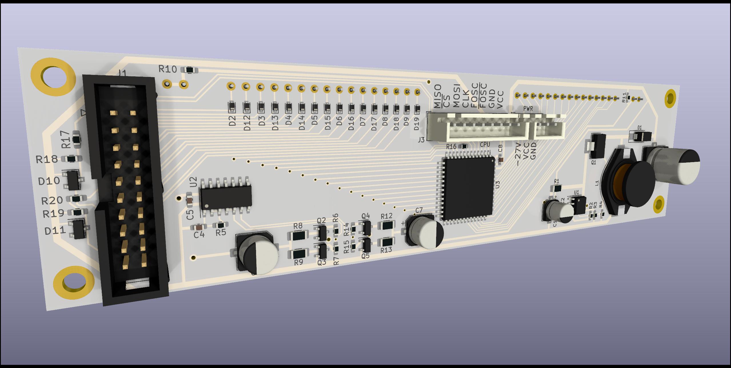
I actually designed the whole module...


...but I had a feeling, I may did something wrong, so I broke the design into pieces, ordered the power supply boards separately, so I can test it, before send the whole module to manufacturing.

The git repo of the design is here:

 https://gitlab.com/suf/suf-electronics-vfd-futaba-15mt67gnk

To be continue..