2016. március 25., péntek

AutomaTales - Why?

Why not?

I'm planning this since we bought our new house back in 2009. I wanted to have some automation right from the beginning. I've a friend who deeply involved in KNX systems. He said, that the cost would be around 10% of the house. I wasn't willing to pay such amount of money at that time, so I just drop the idea.
Of course some automation appeared here and there, but no integration between them.
I had a few attempt to the automation, but it didn't went further.
Just to collect them:
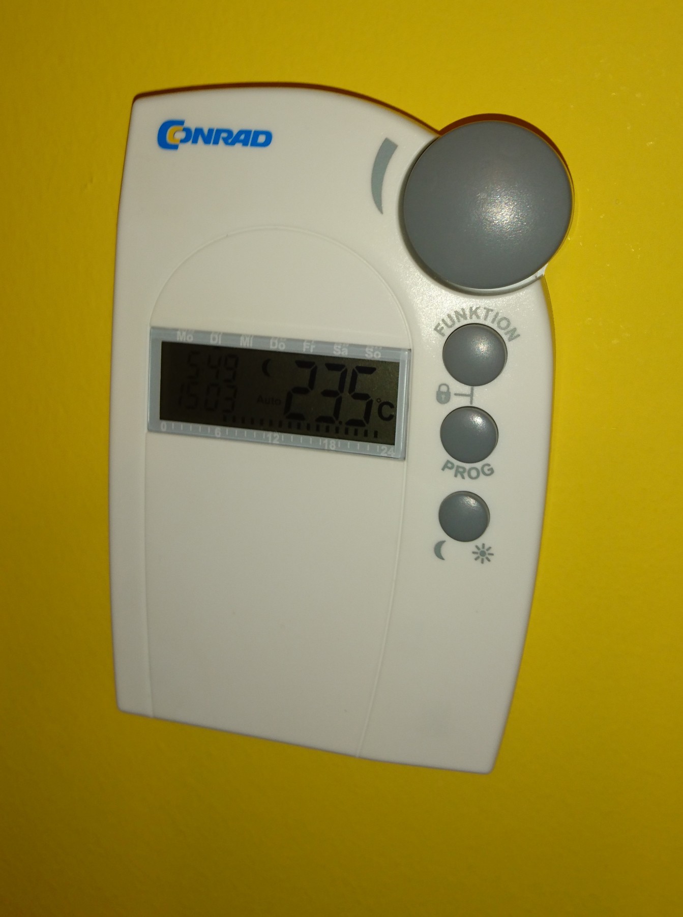
- Bought and installed few Conrad FHT80B thermostats and connecting valves. These are working today as "islands" in the house.


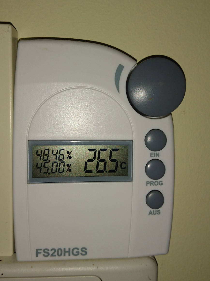
- Bought and installed a humidity sensor and switch (part of the Conrad FS20 system) for controlling my dehumidifier (the integrated control was a heap of crap)


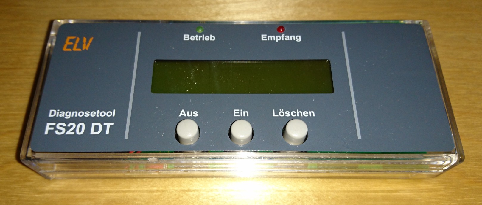
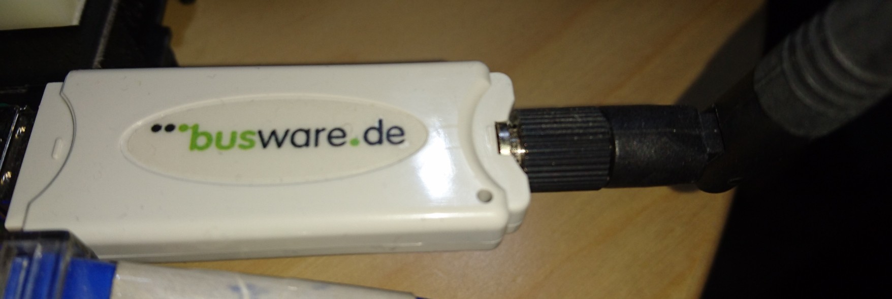
- Bought the computer interface and the code monitor for the FS20 system. The interface is still in a box. The code monitor (or call it debuger) was used a few times


- Bought the CUL v3.2 for controlling the FS20 but kept in one of my parts boxes until now.


- Designed and built a few thermometers, what was planned to be a base project for a future thermostat project what never happened.


As you see almost nothing happened until now.

Why now?
As I'm progressing with my electronics projects, it got some attention from my wife. Attention means task here.
In our garage you can't see anything if you don't switch on the light, but you can't switch it of after you get into the car. The result: if I'm lazy (sometimes I'm) the light left open.
The task: resolve this issue.
It would be a simple solution, to change the switch to a momentary button and add a timer, but....
I want to create a home automation system. This is a good starting point. So rather a simple solution, why not start to build a big one? :-)

2016. február 8., hétfő

Isolation transformer

The reason behind, I started to work on (my still unfinished) CNC Motor driver project is connected to two accidents:
When I exchanged the spindle motor of the CNC from 230W to 400W and the power supply from the unknown underpowered linear crap to a 600W switching mode supply, the later one just blow because of the missing protection diode (my fault)
When I started to repair the above supply, I made the second mistake. I forgot that all mains powered oscilloscope is ground referenced. Second blow, and the repairable supply completely destroyed.
So Is started the CNC motor driver project and on the side I figured out that I definitely need in isolation transformer to avoid such kind of accidents.
I ordered, bought several parts for the transformer - a toroid isolation transformer, an enclosure, switches, connectors, and a nice multifunction panel meter, what able to measure volts, amps, watts, voltampers, and power factor.
All of the parts was lying around in my workshop, as I didn't want to cut, drill the necessary holes to the front and back panel of the enclosure, by hand. I waited to finish the CNC, to do this job.
A few weeks ago I was thinking of testing some power supplies for the home automation project. As I built an electronic load for this, the isolation transformer also appeared as a required tool.
Today I'm in a better situation. May CNC still doesn't work, but the 3D printer does. So what if I just replace the aluminum front and back with plastic, as I did in the electronic load project.
I did it.
Here is the result:


2016. február 1., hétfő

Load

The next big thing I want to work on is my home automation project (but just after I finished some of my actually running thing, like the build siren).
There is a well established central management - OpenHAB - available. Controlling it from whatever you want, also not a problem (Web, iOS, Android applications are available).
Building remote sensors, actuators nowadays is easy. Plenty of it can be found on the internet based on cheap IoT platforms like ESP8266 modules. Connecting different kind of sensors, relays, SSRs, just a piece of cake. Powering this remote thing is much trickier, even the mains line is available. The primary goal of my project to save energy. Consuming much power to measure some device power consumption is really bad idea.
So before I begin the project I'd like to find the most efficient way of powering mains connected sensors (remote sensors without mains connection is a different question - battery powering, energy harvesting, etc. - and I want to deal with it later time). There is a handful of way to design a power supply for this. The requirements:
- As efficient as possible
- Able to provide 200-250mA at 3.3V (maybe 5V) (Power consumption of the ESP8266: http://bbs.espressif.com/viewtopic.php?t=133)
- As cost effective as it can be (I want to build large amount of devices, so the cost matters)
- The electrical isolation is clearly not required. The efficiency is much more relevant
Ok, I don't want to go through all of the possible solution (Resistive, Capacitive, Linear, Isolated and non-isolated switcher, etc.) now. I want to buy/build some, and test them.
For comparing the performance of the power supply variants I desperately need a constant current DC load.
First I was looking around the forums, markets, to find a solution. I was looking for two kind of devices:
1. A cheap one, what can be used as low current load, and not heart to put it aside when I need a pro thing
2. A professional one, what can be used later on, for other projects.
In the first category I found none. Looked around the ebay, aliexpress, tindie, but all of the things I seen there was not suitable for the task or not fall into the first category.
In the second category I found the Maynuo M971x series:


There are quite good reviews about it on the net, but my actual needs doesn't justify $400-600 spending (depending on model it will became the amount together with shipment and customs fees).
So my decision is to build one.
I said before, that I didn't find a suitable cheap one. It is true for the already built models, but on the other hand I found the device what I can build upon. The re:load 2 from Arachnid Labs. http://www.arachnidlabs.com/blog/2013/02/05/introducing-re-load/
Why I not just bought it?
Because it was designed with different requirements. The low current capability and the precision control was not a requirement, but the protection and the self powered operation was.
My design is:
- Powered from independent supply (this time I'll use an AC wall adapter - leftover from my ancient Draytek routers)
- Internal 12V DC supply (higher voltage is useful from many points: OpAmp, selection, optional cooling fan, drive non logic level MOSFET, etc.)
- Changed the current feedback resistor to a much higher value. This decrease the noise and the OpAmp offset problems. On the other side I get 2V voltage drop at 2A load, and I don't want to use this for anything bellow 3.3V.
- Changed the MOSFET to a normal cheap n-channel one (to a type I found in my parts box)
- Added the capability to compensate the OpAmps offset voltage (0.6V negative supply and some trimmers)
- Added range switching capability (0-200mA, 0-2A)
- Changed the normal potentiometer to a 10 turn one
Here is the final schematic:


Built on BreadBoard:


The PCB design:


I choose a metal box for the equipment, but I didn't want to drill several holes to the front panel (the back is a different story it has only one hole what isn't a problem), so designed a 3D printed one.
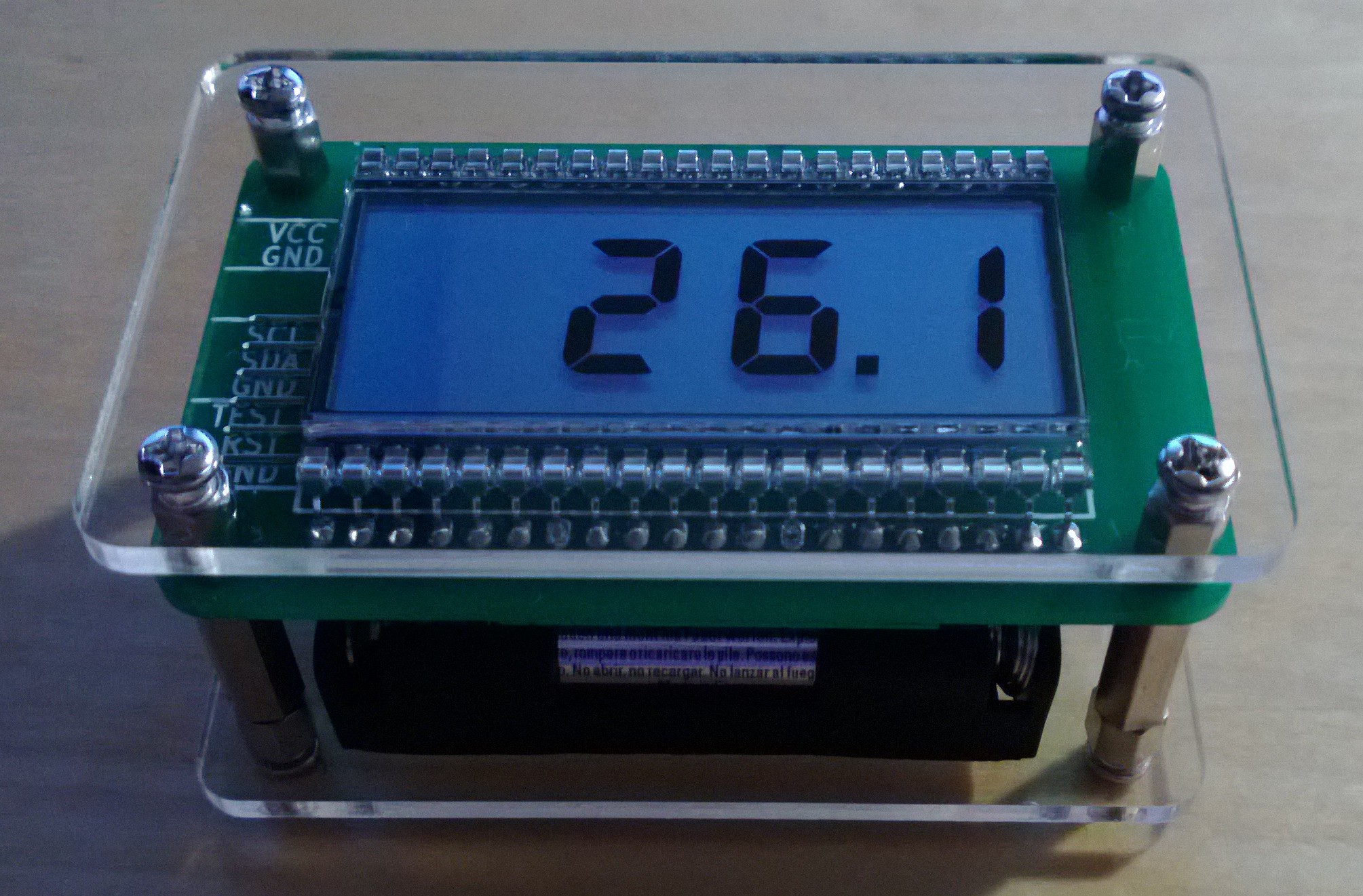
Here is the result. The equipment fully assembled (without the top), measured, working:


2016. január 19., kedd

Motherboard repair

I had a home grew storage server based on Nexenta. It was working for a few years. Unfortunately it wasn't stable. The storage part was rock solid, but the web interface died frequently. In addition I had problems with the boot SSDs.
A few weeks ago finally I migrated everything off it and disassembled the machine. It come out, what I thought is a software problem, maybe a hardware issue:


Two of the same size/type capacitors are dead on the motherboard. As I realized no known (at least to me) markings on the cap, I thought that Intel played incorrectly and used some cheap shitty caps.
Desoldered them, looked around the net, and found out, these are United Chemicon Low ESR caps, so good quality. Maybe this series has some manufacturing issue. Out of the several ones on the board just the 3300uF/6.3V ones died:


8.8uF and 13.4uF in the place of 3300uF not really looks like enough. :-D

2016. január 18., hétfő

MobileVise

For my soldering work I almost exclusively using the StickVise to keep the boards, connectors, etc. in its place on my desk.


As I'm not working in the electronics industry in my daily work, I don't have it in the office just at home. It happened that I was need to solder some audio cable there. Without the StickVise it was a horror.
During the weekend, I was thinking. What would be the solution. I deffinetelly don't wan to carry a StickVise in my bag. I need something like it, but something portable. Than I figured out the solution and the MobileVise born.
After a failed attempt (one of the screw holding clips broke almost imediatelly, because it was too tight, etc.), here is the working one.

The design:


Closed:


Open:


Assembled:


In action:


The movie:


2016. január 16., szombat

Headphone holder

As my 3D printing started to work, I wanted to create some additional things also.
Yesterday, I put in work my long unused (today nonexistent) knowledge in trigonometry. Here is the result:


Meet with my shiny, new headphone holder.
Printed:


And in work:


The files are on the thingiverse

2016. január 2., szombat

3D Printing - seams working

It was a long journey and quite not finished yet. But the current state is satisfactory.
It was more a month ago, when I wrote about it. Many things happened since.
My new printer arrived, I almost fully assembled it, when I realized, that according to all internet sources the included MK8 extruder is a joke. Almost the same kind of as my original one in the Robo 3D. I didn't even want to give a try to it. So I ordered a Bulldog Lite extruder and the well known E3D v6 hotend (to be precise the Chinese clone of it).
The later one didn't arrive, and I wanted to print badly. So I took a deep breath and tried to repair the Robo 3D - millionth attempt.

  1. Repaired the Y axis. It was much easier than I thought. removed the two screws holding the plastic part at the end of the Y axis timing belt. I was able to tighten the belt by 15 teeth (lot).
  2. Replaced the fan holder at the hotend with the good one (the previous was broken and fixed with some adhesive tape) I designed/printed long time ago, lying on my desk.
  3. My assumption about the hanging of the printer electronics because of the overheating of the heat requirement of the ABS looked correct. Based on this I left the cooling as I just want to use PLA now.

The future looked bright, created my first design and...
Just before I started to print, on the old Dell laptop I used to drive the 3D printer the Windows said, that, the hard drive's state is critical and need to be replaced.
SHIT...
The original drive is a 320G one. I wanted to use a 120G SSD
Made a copy of the drive with Clonezilla to a 2T HDD (to resize the partition before copying to the SSD). It took more than three hours, several bad sectors reported.
Checkdisk, resize attempts, etc.
Second Clonezilla to the SSD.
The machine didn't boot.
Ok. I give up. Don't know what data lost (maybe some printer settings and the modified Arduino source of the printer) but I don't want to run into a long Windows repair session either.
Opened one of my shiny new BeagleBone Green. Installed Ubuntu + Octoprint (with a few attempts worked within a day). I felt that the BBG is not powerful enough for the slicing and the legacy Cura installation has some issues. So I decided to do the slicing on my Core i5 desktop and stick with Slic3r what I already used before.
After this everything worked smoothly. Here is the result:


This is the enclosure one of my ongoing projects. It isn't perfect, but I'm satisfied with the printing result so far.