!!!DANGER!!!
The circuit described bellow is dangerous. Using it improperly will kill you. On the other side I may also made mistakes during the design and built. I'll take absolutely no responsibility for it. If you want to build it, please don't ask for circuit board or help. I won't help you.
In my previous posts about the high voltage supply I already wrote about the small electronics able to keep the GND of the DC side on earth potential without isolation.
No this is not voodoo. It just a simple circuit.
The theory:
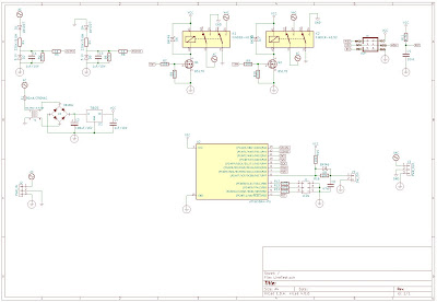
The protective earth connection in the mains connector is connected to the mains null somewhere in your system. Probably somewhere around the utility meter. So if we measure the voltage between the Line and Earth, it will be the full mains voltage. If we measure the voltage between the Null and the Earth, it will be zero. To be able to work with, I draw the following circuit:
This is just two simple zener regulator, what provide the necessary sense signals for the further processing.
I designed a complete circuit around this, with an MCU, a 5V power supply, MOSFETs for driving relays and two DPDT relay.
The board design:
Based on this design I ordered the boards from allpcb. Actually I made a mistake around the design. I bought my relays after I sent the board for manufacturing. The result is that I connected the switched circuit on wrong direction. This means if I build the circuit the relays create a short circuit to the mains.
Throw away the boards (without even soldering a single component), ordered a new batch.
It also arrived within a few days:
The finished board:
I wrote a small arduino code to run the board. It has an ATTINY84 in it. Actually the code would fit in an ATTINY24 easily.
Assembled the whole thing into it's final place:
I connected the final thing to the mains. Switched on the power switch. Everything looked fine, until I pressed the output button.
The main circuit breaker in my house went off. Shitt.
Few more tries. The result get even worst. It killed the mains even switching on the power switch and not the output button.
Removed the phase switching board. Measured. It looked like both of the relays killed. There was a short circuit between the line and the neutral on the board.
Here is when Murphy comes into the picture. How many components buy I usually for my circuits? Way more than needed. Except this case. I had only those two relays on the board. Weekend. I should wait until Monday, to replace the relays.
In the meantime I removed the relays from the board - I hate the THT desoldering.
Removed the cap from one of the relays to be able to make a picture of the burnt contacts:
The surprise come here. No burned contact. Even I made a picture with my microscope. The result is the same:
Nothing, the contacts are intact. Measured the second desoldered relay, what still has it's cap. the result is the same, no sign of the failure anymore.
Just my guess that the heat and mechanical torture of removing the relays of the board resolved the temporal latch-up of the contacts.
Now back to the basics. As I can't find out the source of the problem (didn't wanted to play this game with new relays). I just guessed that the inrush current of the capacitors causing the problem (as I wrote earlier, I had problem with it already). So I hacked a solution. Together with the new relays I bought some inrush protector NTCs. It isn't an ideal solution, but hopefully will be sufficient. Hacked a PDU board to accommodate the NTCs. I've a few spare anyways:
The relays replaced. The whole thing works as expected.
I'm still thinking about the proper solution. The device is a tool and not a target for me. So it may not worth the effort to build a second version.


Nincsenek megjegyzések:
Megjegyzés küldése