2018. február 20., kedd

Micro:bit - self hosting

If you want to use the Microsoft MakeCode for programming your micro:bit you can use the online editor hosted by microbit.org:
https://makecode.microbit.org/#
Actually it has some drawbacks:
The site has no login. So you don't have your own environment online.
It store your projects on your computer (but actually I don't know where - I didn't find documentation on i). I'm working on my projects on three different computers. This makes virtually impossible to transfer or put into secure place (git server) my projects.
There are situations when you want to work on your things when disconnected from the internet.
Anyhow. It is possible to run the environment on your own computer:

  1. Install NodeJS. You can download it from here: https://nodejs.org/en/
    The current LTS version is sufficient
  2. Create a folder on your computer to store your projects, for example c:\microbit
  3. Open a command prompt and execute the following commands:
    npm install -g pxt
    npm install

    Close the command prompt (necessary for the environment variables just created)
  4. Open a command prompt and navigate to your folder:
    c:
    cd microbit
  5. Execute the  following command:
    pxt target microbit
Now your environment is ready. You can start it with tho following command:
pxt serve
Next time when you want to run it, this is the only command needed.
When it starts you can realize two things:

  • The command prompt you'll see a continuously rolling error message:
    "Error: ENOENT: no such file or directory, open 'C:\microbit\node_modules\pxt-microbit\targetconfig.json'"
  • There are no installable package in the "add packages" list just the integrated ones:

This means, you can't add any add-on.
The missing file is the descriptor of the add-on packages. You can download a template from here:
https://github.com/Microsoft/pxt-microbit/blob/master/targetconfig.json
So, if you stop the server (Ctrl-C), download this file into the folder mentioned in the error message, than restart the server (pxt serve). The error message will disappear and you can see the add-ons:


This file also can be used to add our own add-ons if we find something on the internet and want to add to our environment.

2018. február 19., hétfő

Anettka (Anet A8)

In the last year I was thinking about a 3D printer in my office. Even I was bringing my Geeetech printer there for a week.
As I see the prices dropping, I couldn't resist anymore. I ordered an Anet A8 from the German eBay. It cost me €130 + €15 shipping. It arrived in a few days.


It took me just a few hours to assemble. Started on Friday late afternoon, finished on Sunday, but mainly I did other things during the weekend. I think the net build time was around 6-7 hours.
Here is my experience with the whole thing. Mostly random thougths:
  • The build instructions I found is clearly not for the kit I bought. I think the printer has several revisions, and therefore the documentation need to be handled "creatively".
  • The whole thing is easy to assemble. If you get use to the nuts inserted into the acrylic frame.
  • I don't understand the provided screw drivers. There is no screw fits to it.
  • The quality of the timing belt provided is the worst available on the market. It is the plastic kind without reinforcement.
  • The tightening of the timing belts are always an issue. Same here. For the Y axis it can be handled by loosening the screws of the motor and the pulley on the other end before mounting the belt ends to the Y carriage.
  • For the X axis the situation is not as good as for the Y. The construction itself has design flows. There is nothing in your hand to tighten the belt, but even if you can handle it, the axis is tightened against the Z guiding rails (and not against the X rails), what create a force to those rails, what has to be avoided. Here comes the one and only modification I made for the original build (I'm planning several after the first working build). I printed this:
    https://www.thingiverse.com/thing:1683070


  • Fortunately my Geeetech printer was able to do this, so I didn't struggle with the build without this component.
  • The rumpled masking tape on the build platform is a joke not something you can print on.


  • The labeling of the various cables are excellent. It makes easy to connect everything together.
  • The UI of the firmware is extremely slow. I don't get why need to animate on alphanumeric display with an 8 bit processor (Marlin is coming).
  • The extruder: pro: it has an all metal heathbreak - no teflon tube inside, con: can't be removed, disassembled without loosing the bed leveling. It is a problem without autoleveling


And the first test print:


2018. február 10., szombat

"Lightronome" 1. - The light based metronome

I got a request, to design and build an electronic metronome. You can find several on the market, but the problem it is ether producing voice or the classical mechanical metronome. The requirement here was a visual effect. To be precise four LEDs for 4/4 beat. It is required for drumming where you have no chance to hear the clicking (or maybe just through headphones).
So the idea:

  • Pick an MCU (in my case it is an ATTINY85)
  • A three digit LED display to see the beats per minute
  • Two buttons to change the speed
  • Four LEDs (in my case four RGB LEDs to be able to change the color from code)
  • Power Supply, and the usual things needed for such circuit.

If you check the things above, you can quickly realize, that there is not a chance to drive the things above from an ATTINY85.
Here come into the picture an article I wrote earlier: http://pakahuszar.blogspot.hu/2018/01/tm16xx-arduino-library.html
The library I wrote for the Titan Microelectronics display drivers originally made for this project. So you can add a TM1637 to the picture above. It able to drive 6x8 LED segments, plus read 2x6 buttons. It is more than enough for LEDs, display, and the buttons.
After writing the library, the actual code of the Metronome was quite simple.
First I built the whole thing on breadboard, but using an Arduino UNO instead of the ATTINY85:


After the successfull test, I designed and ordered the board for it.


It arrived in a week:


Started to populate it - here comes the problems:

  • I chosen a wrong size package for the ATTINY85, so I have to bend the pins to be able to solder in
  • The micro USB connector wasn't far enough from the edge
  • The 3.5 Jack had two missing holes.

Those was easily correctable.
So the build (without the display):


After resoldering the ATTINY for a few times, I was able to download the code, but nothing appeared on the display or the LEDs.
Scratching my head. Then I realized, that the ISP connector has all of the pins required to drive the TM1637. So I connected this external display to it:


It was working.
I started to measure the board, and instantly realized the problem.
The VCC and GND pins of the TM1637 was swapped. How this happened?
I mirrored the TM1637 part in the KiCAD. After this the GND pin went to the top of the drawing and the VCC to the bottom. After this I connected the power pins as usual. The VCC to the top and the GND to the bottom. IDIOT!!!!

I categorized this error as uncorrectable, So I made some design changes: the three issues from above and this, plus added the pinout table for the ISP.
New order, one week waiting, board arrived:


Built it once more.
There were some numbers on the display, but it didn't work as expected. I realized two more design errors:

  • The display anodes were swapped so the number was readable from right to left
  • The LEDs didn't lid - It was rotated by 180 degrees

Rewrote the code for the display, desoldered the LEDs and added new ones rotated (those LEDs are unable to withstand the heat fro the heathgun)
Now it is working as expected.
In the meantime I designed and printed the plastic box:


The mounting hardware still need some work, but the device is working now:


There are a few comments to add:

  • The mounting hardware still need some work, so you can expect some writing about it
  • The two currently used buttons also has remote capability through a 3.5mm Jack. The external buttons drive the internal ones through optocouplers. This is not isolated just there for providing some noise immunity.
  • There are place on the board for crystal. I don't know if such precision is required, but I didn't populated yet.

I'm thinking about selling this device if somebody is interested in. I try to find out if there is demand for such device. I've a few idea for further development. If you have suggestions regarding this please leave it in the comment.

2018. február 3., szombat

BBC micro:bit and its speed

I'm experimenting a lot with BBC micro:bit recently. It is designed as education tool for kids. According to the microbit.org's intention it can be programmed in Block editor, JavaScript and Python.
Since it arrived to the market the maker community and commercial companies put big effort into it, so today it can be used in large amount of environment.
The original programming tools are good for learning, but not really targeted for professional MCU environment. If somebody want to learn something like this, must step forward. This has many aspects why. Here I'd like to show, that:

  • The micro:bit hardware not the limiting factor in first place
  • You can achieve much more speed from the MCU with those environments

About the board itself:
The micro:bit's core is a 16MHz ARM Cortex-M0 based bluetooth capable Nordic Semiconductor MCU. It is the same what used in commercial devices. The board itself also contains a second processor, an NXP Kinetis device. This second processor is responsible for the communication with the PC where we programming the main MCU from.
This second MCU is our ticket to the professional programming environments.
If you used micro:bit block editor before, you know if you connect the micro:bit to your PC, you will see a drive and you can drop your compiled code there. This drive emulator is handled by the NXP processor.
But this does more than that. It is acting as a debug probe also. It allows single stepping, register reading, etc. in the Nordic MCU, allowing the user the efficient debugging procedures with an developer environment it allows that.
Even you can choose between two different debug probe. The micro:bit arriving with DAPLink (CMSIS-DAP) probe, but it can be changed to Segger J-Link probe if your environment need this.

Now about the speed. I used a small test to show what can we achieve in various environments. The test does nothing else just switch an I/O pin of the device alternating 0 and 1 as fast as possible.
I used three environments for demonstration:

  • Block editor/Javascript - The original environment
  • Arduino - The first choice tool of Makers, Hobbiest around the globe
  • Segger Embedded Studio - One of the heavy professional tools (I choose this as it was the fastest to setup and started to work on the first touch)

The first try - It is written originally in JavaScript instead of Block editor as the Block editor unfortunately has no XOR function. It show what is happening if we alternate our output in the "forever" block:


How this look like in the Block editor:


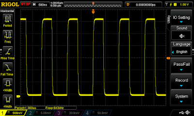
I connected the output to an oscilloscope to measure the output frequency and see the waveform:


20.8Hz - Ouch it hurts. This means that our code in the forever block is called around 40 times in a second. This is extremely slow. I guess it is the result of the task scheduling of the operating system beneath us.

Let's do another test with this environment. But this time using our loop for switching the output. This is written in the Block editor as it has nothing can't be achieved there:


Just to see, it is here in JavaScript:


And the result:


84.7kHz - much better, but still, it needs 189 clock cycles to run this loop (calculated from the 16MHz clock)

Now go a bit further. The Arduino environment can be used for the micro:bit based on this:
https://learn.adafruit.com/use-micro-bit-with-arduino/install-board-and-blink

First I tried the same, using the environment's loop:


The result from the oscilloscope:


214kHz, much better. It is around 75 clock cycles.

Check the same with own loop:


Bit better but not substantially:


272kHz - 59 clock cycles

And finally the Segger Embedded Studio - as you can see, here the CPU initialization tasks are also in your control:


And the result:


943kHz - 17 clock cycles. If you want to achieve better result, you must go down into assembly level, what I not intend to do now.

From the things above, you can see a little slice of the picture.