2023. május 29., hétfő

Keithley 2700 - Repair

 I couldn't resist. Found this puppy faulty on the eBay.


It doesn't turn on. Even consume zero current from the mains.

For a quick look: the fuse is intact. Tested the AC connections from the mains transformer. Nothing come out. Ok, so either the mains transformer or the mains connector module (connector, voltage selector, mains switch) faulty.

Checked the Mains connector module. Unfortunately the available service manual is useless. So with the mains module, done some reverse engineering.

Here is the transformer's connection:


Measuring the transformer I found out, that the 100V winding is demaged.

So, I connected the 100V - 220V cables (blue and gray) to my variac, and set the voltage to 120V.


Here are the results:


For the first sight, it looks like, it has no other issue than the faulty mains transformer. Now I need to find a replacement unit, or somebody, who is able to wind a new one for me.

2023. május 22., hétfő

Analog Multimeter 3. - PCBWay Review

My boards arrived Yesterday from PCBWay.

As this is the first time I use them as board house I'd like to write a small review here.

I'm ordering PCBs from various manufacturers in the last 14 years. I started with some local manufactures. Those guys had horrible prices and not so good quality (anything above the single side board had additional cost, etc.)

10 years ago I changed to the board houses located in China. As my projects mostly has no time constraints, the long delivery time hadn't be an issue to me.

There were a certain PCB size what manufactured on the low cost ($5 + shipping). This started with 50x50mm, then become 70x70 and lately 100x100. Almost all of the manufacturers today provide 10pcs 100x100mm two sided, masked, silkscreen printed boards for 5$ + shipping.

This is where we stand today.

Lets check the order process of PCBWay. I had a simple 100x50mm board, for prototyping my SuperTracking regulator (based on Walt Jung/Jan Didden design).

It is a great thing to have a gerber viewer and automatic size calculator in your order process. Here the PCBWay site tricked me a bit. I didn't find this feature on the first sight. It is not reside on the main ordering page you see at first. You need to switch to the "Quick-order PCB" page to get this.

I absolutely love this feature:

It means you order your PCB with HASL (tinned) finish and if you are lucky you get ENIG (gold plated) finish. To understand, the manufacturers put your hobby projects into the big orders process. If you tick this checkbox, you may get a gold finish. The manufacturer on the other side has greater flexibility where they put your order. This is an absolutely win-win situation.

We care about the environment. The EU doesn't allow lead based solders for a while in the consumer electronics devices. At the board houses, you can select between the leaded and the lead free finish. The manufacturers I seen previously charge extra for the lead free finish. This come from PCBWay with no additional cost.

If you ordered already PCBs, you always find a tiny order number on your board somewhere. In most of the cases this doesn't cause any problems. You have the paying option to remove this number. This is not always necessary. Check my previous design, what is the scale of the meter under design. There could be a problem to see this number on the visible area of the board. Here you can add special request written where you want to place this number. At other sites I seen a method, you can add a specially formatted text to your silkscreen where the manufacturer can put this number. I feel this point as room for improvement.

At PCBWay you pay your order after the review (in few hours - it took me a day, probably because I ordered my board during the weekend). Other manufacturers require the payment upfront. I think it is matter of taste. I prefer this method. It give me some time to review myself if everything is ok, I didn't make a mistake at the order (unfortunately paying upfront caused me trouble in the past).

One additional thing about the order process. Providing and stating to provide IOSS (Import One-Stop Shop) is a help for the EU customers from two point: the order arrive faster and you don't need to do the paperwork at the local customs or tax authorities.

The order of mine arrived on Monday.

The quality of the boards are excellent. Didn't find any issue with it. This is the quality I expect from the boards I want to use.

I was eager to populate it as soon it arrived. I was sure that all of the required components arrived. Jumped into the build. Immediately realized that three parts are missing.

One is the voltage reference I intend to use. It is my fault, forget to order it.

The other two is the dual OpAmp and the small NPN transistor. I got a message from Mouser: "Shipments of this product must be direct to an END CUSTOMER from an AUTHORIZED DISTRIBUTOR only.  Your customer must order this product directly from Mouser or another authorized distributor."
Come on! I never sold components as a reseller. I'm just an engineer who time-to-time fix things, design equipment.

Contacted Mouser, It took around three days to settle this.

So yesterday finally ordered the remaining components. Waiting for the arrival.

2023. május 10., szerda

VFD Mania 3. - Reverse engineering, filament supply

In the last few years I collected many VFD tubes. In the last weeks, a bit cleaned it up, unsoldered a few to have just bare tubes.


This is not all, but most of it what I currently have.
I wanted to make a catalog for myself with the pinouts. On the internet there is no common source of these. No datasheets, etc.
So the reverse engineering is required. For this I built a small, simple device (it took less than an hour from the idea).
For testing I need a 2.5V as a filament supply (may not the ideal solution, but good enough for testing), and something (12V good enough), for the anode and gate.
So, I built this:

The two blue banana can be connected to the filament pins, the two red sockets for the gate and anode. With this I can quickly find the segments.
Currently documenting it to a simple Excel sheet, but looking for a better solution, to able to publish it.
Finally took the time to test the previously designed/built filament supply.


It started to work immediately, but...


The waveform is horrible.
Superposed to the -27V supply is not much better:


My first hint was instability at the last inverter (but it was highly unlikely). Testing, the previous circuit state generated this:


I got a hint from a group (I would try it myself anyway), to check the supply voltage.
It looks like, the 20cm cable I used has too much resistance.
Adding a 1000uF capacitor to the input voltage of the module produced this:


Still has some overshoot, but I think, I'll be able to handle this at the final design.
Next, I'll order the complete PCB for the Futaba 15MT67GNK and the Princeton controller IC.

2023. május 8., hétfő

Analog Multimeter 2.

Since the first post on my analog multimeter happened a few things.

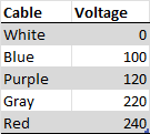
I was thinking about the scale plate. If I order it as a PCB, why not to add some useful electronics to it. And I did. Adding a few LEDs will give a perfect backlight for the meter.

Also, I figured out, what to add to the back side. I've a few from this meter in the box with center zero configuration, so I added the same layout (with the LEDs) to the back side with center zero scale. Removed the "V" designator from the original design to add some versatility.


The back cover, with the mirror (3D printed insert + mirror foil) assembled:


Let there be light:


The assembled panel meter (no, I will not keep this scratchy plexi cover in the final instrument):


On the side, I started to work on the electronics. As it still far from ready, a few things are already settled. First of all the power supply voltages - Yes, you can tell it is too early, without the final design, but by my opinion, is a right time to try out some things.

What I already know about the analog section that I need a symmetrical, very low noise design, with the minimum achievable offset voltage - It is my assumption that the supply voltage is not really mater in a certain range, but the positive and the negative rail should match as much as possible.

So I "designed" an analog power supply. This first version is just to prove my concept, definitely not the final one. It will provide +-5V, roughly 1A. It is based on Walt Jung and Jan Didden's work called "SuperRegulator". Actually, I changed the reference to an MCP1502-25 from Microchip, changed the level shifting zener to LEDs (according to Walt Jung, it generate noise), and the negative side is not a separate regulator, but a tracking one. Also the Op Amps supply will be symmetric.

The design now is SMT except the power elements (two power transistors and two pre-regulators) also used a DIP socket for the Op Amp, to be able to try out different ones. My plan is OPA2180, but we will see, what is the best option.


I also designed the board for it:


Roughly a week ago I got a message from PCBWay marketing, that they recognize my work, and intend to sponsor my efforts with the PCB manufacturing.


This is an excellent news for me. This board is ordered from them. I eagerly waiting to arrive, and be able to review and also build this design. I'm looking forward to work with you guys.

My planned design for this meter is full of Op Amps. There is an Op Amp competition running at Hackaday currently: https://hackaday.io/contest/190312-op-amp-challenge.
I'm thinking about to enter with the part of this instrument.
Actually a circuit is "itching" in me for a while. This is a precision rectifier. Yes, you can tell, this is a well known, commonly used thing, but ...
Yes, that "but" is always there. I seen something as a patent entry from Microsoft (yes, this is funny, why Microsoft is trying to get a patent on an analog circuit), what, as it looks like not accepted.
This is what I feel a really good solution. I don't found drawbacks, but I'm really not qualified to judge this.
So, I started to design something based on that. Currently it is just a simulation, not using real components, it is just for functional proof.

The circuit:


It is based on an inverting and a non-inverting imput Op Amp (keeping constant input impedance, and creating inverted output also), a comparator, an analog switch and an output buffer.
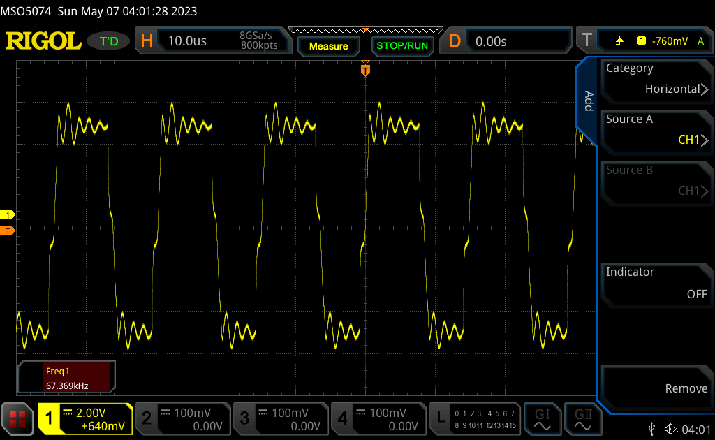
Here is the produced waveform:


Don't forget, right know it is only theoretical, and low frequency. In the analog multimeter project I not even planning to use it for rectification, rather for automated polarity switching.
Next, I'll design the real circuit and PCB for not just test the functionality, but also the performance of it.
This is all for today. I'll continue (hopefully soon)