This is not all, but most of it what I currently have.
I wanted to make a catalog for myself with the pinouts. On the internet there is no common source of these. No datasheets, etc.
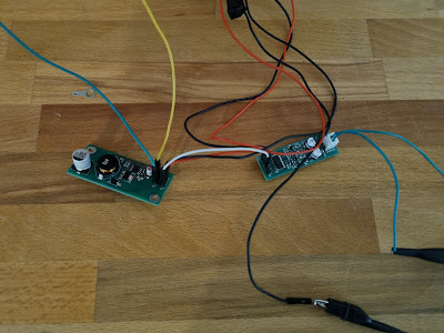
So the reverse engineering is required. For this I built a small, simple device (it took less than an hour from the idea).
For testing I need a 2.5V as a filament supply (may not the ideal solution, but good enough for testing), and something (12V good enough), for the anode and gate.
So, I built this:
Currently documenting it to a simple Excel sheet, but looking for a better solution, to able to publish it.
Finally took the time to test the previously designed/built filament supply.
It started to work immediately, but...
The waveform is horrible.
Superposed to the -27V supply is not much better:
My first hint was instability at the last inverter (but it was highly unlikely). Testing, the previous circuit state generated this:
I got a hint from a group (I would try it myself anyway), to check the supply voltage.
It looks like, the 20cm cable I used has too much resistance.
Adding a 1000uF capacitor to the input voltage of the module produced this:
Still has some overshoot, but I think, I'll be able to handle this at the final design.
Next, I'll order the complete PCB for the Futaba 15MT67GNK and the Princeton controller IC.


Nincsenek megjegyzések:
Megjegyzés küldése