A következő címkéjű bejegyzések mutatása: Electronics. Összes bejegyzés megjelenítése

2023. június 12., hétfő

Reference Resistors

A friend of mine asked me for a quick project (finally it become not so quick, but just because the time it required the parts to arrive).

He is installing pool and other water handling related systems. One of the pool measure system has PT100 temperature sensor input what need calibration. The proper calibration equipment cost a fortune. Actually he only need two reference point. For this he asked me to make some reference resistors in a box what is precise enough and has low tempco.

The values are 100 ohms and 119.4 ohms what is weird a bit. Looked around and find the required resistors in 0603 and 0805 size (100 and 120 ohms 0.01% 2ppm) around $10 each. For the 119.4 ohms I planned 24k in parallel with the 120 ohms (bit less precision as there is not needed better).

I bought some tiny aluminum boxes from the AliExpress. The idea to change the front plate of the boxes to a PCB add the screw-in banana sockets and put the resistors to the back of the boards.

It looks like this:

It was manufactured by PCBWay in the usual excellent quality - Thank you!

I was a bit afraid, if they can follow my request and put the order number to the already crowded component side, but it was managed without problem. It arrived together with my VFD project board, what I'll write about later.


The board soldered (Yes, it is a joke. Only one single resistor in this case)


Some measurements


If I count the cable and the plugs contact resistance is the result get even better. I'm satisfied with the result.

And the final boxes (the request was about two units.


I put two resistance values into a single box. The only thing left is to print some labels on it with the values.

2023. május 29., hétfő

Keithley 2700 - Repair

 I couldn't resist. Found this puppy faulty on the eBay.


It doesn't turn on. Even consume zero current from the mains.

For a quick look: the fuse is intact. Tested the AC connections from the mains transformer. Nothing come out. Ok, so either the mains transformer or the mains connector module (connector, voltage selector, mains switch) faulty.

Checked the Mains connector module. Unfortunately the available service manual is useless. So with the mains module, done some reverse engineering.

Here is the transformer's connection:


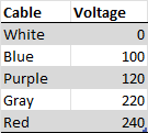
Measuring the transformer I found out, that the 100V winding is demaged.

So, I connected the 100V - 220V cables (blue and gray) to my variac, and set the voltage to 120V.


Here are the results:


For the first sight, it looks like, it has no other issue than the faulty mains transformer. Now I need to find a replacement unit, or somebody, who is able to wind a new one for me.

2023. május 10., szerda

VFD Mania 3. - Reverse engineering, filament supply

In the last few years I collected many VFD tubes. In the last weeks, a bit cleaned it up, unsoldered a few to have just bare tubes.


This is not all, but most of it what I currently have.
I wanted to make a catalog for myself with the pinouts. On the internet there is no common source of these. No datasheets, etc.
So the reverse engineering is required. For this I built a small, simple device (it took less than an hour from the idea).
For testing I need a 2.5V as a filament supply (may not the ideal solution, but good enough for testing), and something (12V good enough), for the anode and gate.
So, I built this:

The two blue banana can be connected to the filament pins, the two red sockets for the gate and anode. With this I can quickly find the segments.
Currently documenting it to a simple Excel sheet, but looking for a better solution, to able to publish it.
Finally took the time to test the previously designed/built filament supply.


It started to work immediately, but...


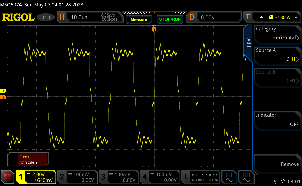
The waveform is horrible.
Superposed to the -27V supply is not much better:


My first hint was instability at the last inverter (but it was highly unlikely). Testing, the previous circuit state generated this:


I got a hint from a group (I would try it myself anyway), to check the supply voltage.
It looks like, the 20cm cable I used has too much resistance.
Adding a 1000uF capacitor to the input voltage of the module produced this:


Still has some overshoot, but I think, I'll be able to handle this at the final design.
Next, I'll order the complete PCB for the Futaba 15MT67GNK and the Princeton controller IC.

2023. május 8., hétfő

Analog Multimeter 2.

Since the first post on my analog multimeter happened a few things.

I was thinking about the scale plate. If I order it as a PCB, why not to add some useful electronics to it. And I did. Adding a few LEDs will give a perfect backlight for the meter.

Also, I figured out, what to add to the back side. I've a few from this meter in the box with center zero configuration, so I added the same layout (with the LEDs) to the back side with center zero scale. Removed the "V" designator from the original design to add some versatility.


The back cover, with the mirror (3D printed insert + mirror foil) assembled:


Let there be light:


The assembled panel meter (no, I will not keep this scratchy plexi cover in the final instrument):


On the side, I started to work on the electronics. As it still far from ready, a few things are already settled. First of all the power supply voltages - Yes, you can tell it is too early, without the final design, but by my opinion, is a right time to try out some things.

What I already know about the analog section that I need a symmetrical, very low noise design, with the minimum achievable offset voltage - It is my assumption that the supply voltage is not really mater in a certain range, but the positive and the negative rail should match as much as possible.

So I "designed" an analog power supply. This first version is just to prove my concept, definitely not the final one. It will provide +-5V, roughly 1A. It is based on Walt Jung and Jan Didden's work called "SuperRegulator". Actually, I changed the reference to an MCP1502-25 from Microchip, changed the level shifting zener to LEDs (according to Walt Jung, it generate noise), and the negative side is not a separate regulator, but a tracking one. Also the Op Amps supply will be symmetric.

The design now is SMT except the power elements (two power transistors and two pre-regulators) also used a DIP socket for the Op Amp, to be able to try out different ones. My plan is OPA2180, but we will see, what is the best option.


I also designed the board for it:


Roughly a week ago I got a message from PCBWay marketing, that they recognize my work, and intend to sponsor my efforts with the PCB manufacturing.


This is an excellent news for me. This board is ordered from them. I eagerly waiting to arrive, and be able to review and also build this design. I'm looking forward to work with you guys.

My planned design for this meter is full of Op Amps. There is an Op Amp competition running at Hackaday currently: https://hackaday.io/contest/190312-op-amp-challenge.
I'm thinking about to enter with the part of this instrument.
Actually a circuit is "itching" in me for a while. This is a precision rectifier. Yes, you can tell, this is a well known, commonly used thing, but ...
Yes, that "but" is always there. I seen something as a patent entry from Microsoft (yes, this is funny, why Microsoft is trying to get a patent on an analog circuit), what, as it looks like not accepted.
This is what I feel a really good solution. I don't found drawbacks, but I'm really not qualified to judge this.
So, I started to design something based on that. Currently it is just a simulation, not using real components, it is just for functional proof.

The circuit:


It is based on an inverting and a non-inverting imput Op Amp (keeping constant input impedance, and creating inverted output also), a comparator, an analog switch and an output buffer.
Here is the produced waveform:


Don't forget, right know it is only theoretical, and low frequency. In the analog multimeter project I not even planning to use it for rectification, rather for automated polarity switching.
Next, I'll design the real circuit and PCB for not just test the functionality, but also the performance of it.
This is all for today. I'll continue (hopefully soon)

2023. április 9., vasárnap

Rubidium frequency standard 1.

It took nine years, to pull this project out from the drawer:

https://pakahuszar.blogspot.com/2014/03/project-idea-rubidium-frequency-standard.html

When I tested my HP 53131A and HP 53181A (already sold) frequency counters (also checked my oscilloscope and function generator), I realized, that all of the equipment a bit off in frequency (even the HP with its HS Oven).

I need some lab standard. As my lab is in a basement of a big building and the only access for the open sky is on the street side, where I can't put antenna, so I think the GPSDO is out of question. The other option would be a DCF-77 based solution (maybe based on this: https://www.qsl.net/dl4yhf/dcf77_osc/index.html), but it would take a while to experiment

So the best thing I can use is the FE-5680A rubidium standard, what I bought at the $50 era (now you can get it around $200).

I bought a Geppetto Electronics breakout board for it https://www.tindie.com/products/nsayer/fe-5680a-breakout-board/. Before try with it, I looked around and realized, that some of the FE-5680A modules on sale has internal 5V supply, and supplying it externally, may harmful for the unit.

So I just pick a DB-9 screw breakout for the first test.


It started without additional supply. I was able to get the lock signal, but nothing else.
I was able to identify:
Pin 1 - 15V
Pin 2 - GND
Pin 3 - Lock indicator
Pin 5 - GND
But nothing else. Most probably the narrow 1pps signal is present on the Pin 6, but wasn't able to get it for the first try (later, I'll retry it)
Looked around many sources. It look like it is an older model.
Found a few links. Somewhere in the documents were some information about Mathias Bopp's pdf file named: precise reference frequency rev 1_1.pdf
Actually I have the link, just the file is not downloadable from there. Here come handy, that I'm in the IT for a long while. Some digging in the Internet Archive resolved this.
It looks like, this document contains the most useful information about my specific unit. Probably other people will need it, so I republishing it here: precise reference frequency rev 1_1.pdf
About this specific unit:
The Good:
It has the DDS board inside. Theoretically it can be programmed to any frequencies from 10Hz to 20MHz.
The Bad:
The RF signal is not present on the DB-9 connector, so modification needed. In addition the phase noise (jitter) of the DDS not as good as a VCO controlled OCXO could be. It could cause problems at high frequency usage.
The Ugly:
It is a facepalm situation when I first seen how some of the ham operators killed the other ways proper RF connector on the DDS board.

One of my parts box I found an IPX - SMA pigtail cable. Tried it, and the IPX connector perfectly fit into the RF connector on the DDS board - Win 1!


As I'm still not an RF guy, don't have RF converters, cables, etc.
Found locally SMA - BNC adapters to run my first measurements with frequency counter and oscilloscope. I was able to pick it in one day. - Win 2!


Ok, now connect everything together and measure.
Trying to screw the SMA adapter to the pigtail cable. Doesn't fit. What?
Then realized. Wasn't careful enough. I just took a quick look to the pigtail cables I have. Now checked more thoroughly. It is RPSMA and not SMA.  Ouch.


Anyway. Measure, to get some results:


Wow! It looks like my frequency counter is spot on. Showing 0.75Hz difference between the rubidium standard and the OCXO in the counter (from this, I can see that the standard is set to 2^23 Hz instead of the 10MHz) - Yes, probably I can get better results, when this unit is boxed, with the proper connectors and left switched on for a while.
Let see, how it looks like on my Rigol oscilloscope.


It show 8.4210MHz. I definitely not happy with that. I'll try to figure out, how can I adjust it a bit.

I stand here with this unit.
What is next:
  • Figure out the RX/TX connection and set it to 10MHz
  • Add a PSU and box the unit.
  • Do some performance measurements (actually I'll need an SA, what I don't have right now)
Further plans/ideas (maybe or maybe not):
  • Lock an OCXO to the 1PPS signal to enhance the phase noise performance, if necessary
  • Create a user interface (MCU, probably VFD display, rotary encoder), to be able to change the output frequency. This most probably need the modifications described in the pdf above to get a better performance from the output filter.
To be continued...

2023. március 24., péntek

New Arrival 11. - kind of...

New Old arrival.

The things I picked up today are not new, not even for me.

A friend started a community lab a few years ago. I donated to him a bunch of test equipment. Actually I had a much smaller lab myself, and I over collected things.

Then came the COVID. This killed the the lab. 

My friend finally gave up, repurposed the lab, for his own purposes.

Most of the equipment I gave, has not too much use for him. He felt, that it wouldn't be appropriate, to give away those things. So we agreed, that the equipment he doesn't need, or used come back to me.

Today I went to the lab, and picked those up.

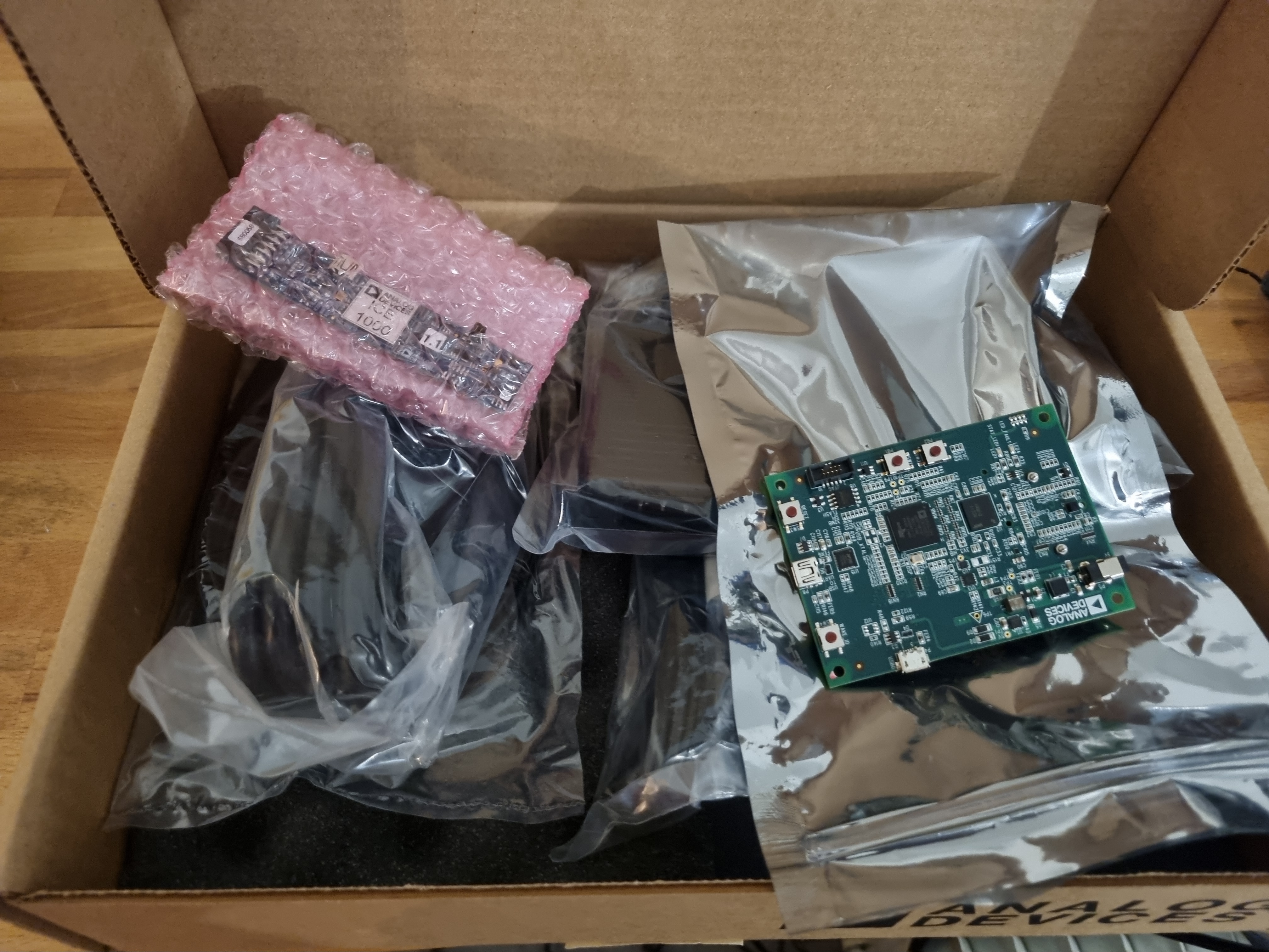
Bunch of FreeScale (now NXP) development boards, a CubieBoard, two BeagleBones, and a big Analog Devices Backfin development kit.

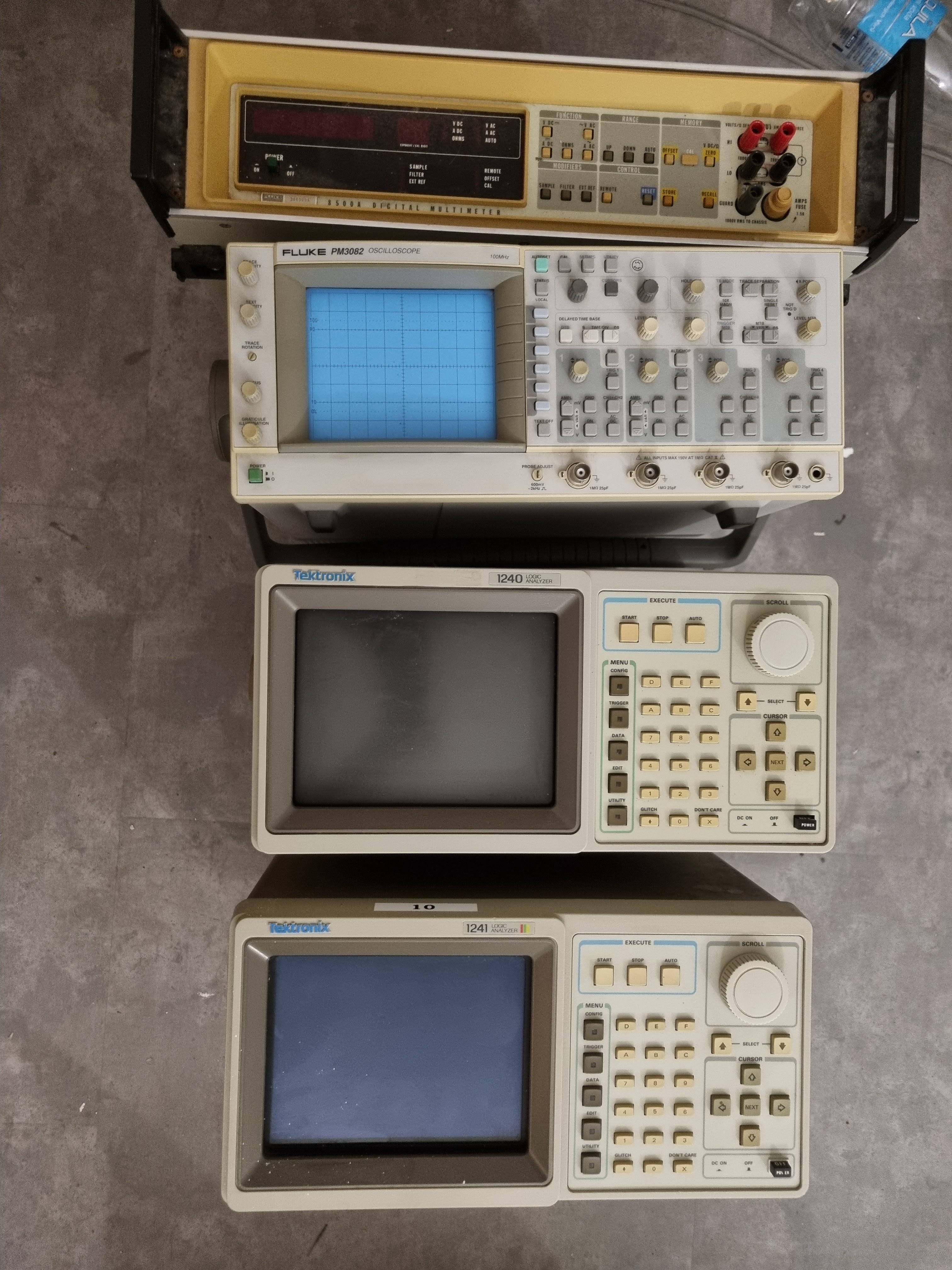
Also some nice test equipment:

Fluke 8500 multimeter, a Fluke/Philips PM3082 Oscilloscope (Even, I have a second one from this), a Tektronix 1240 and a 1241 logic analyzer.

For the logic analyzers I even have the original carrying case for the probes (with full of probes).


My plan is to switch on, test, and sell most of the things above, as I barely need them (may keep, some of it, but this is not the main plan)

2023. március 23., csütörtök

VU Tower

I have children (a boy and two girls).

I always have in mind to connect my hobbies to my family. It not always turns the way I'd like, but not this time. For precious moments time-to-time I make presents myself. Like the repurposed radio for my mother for Christmas.

During the last weekend was one of my daughter's 14th birthday. She is moving to party age soon. What would be better than something with lights connected to music.

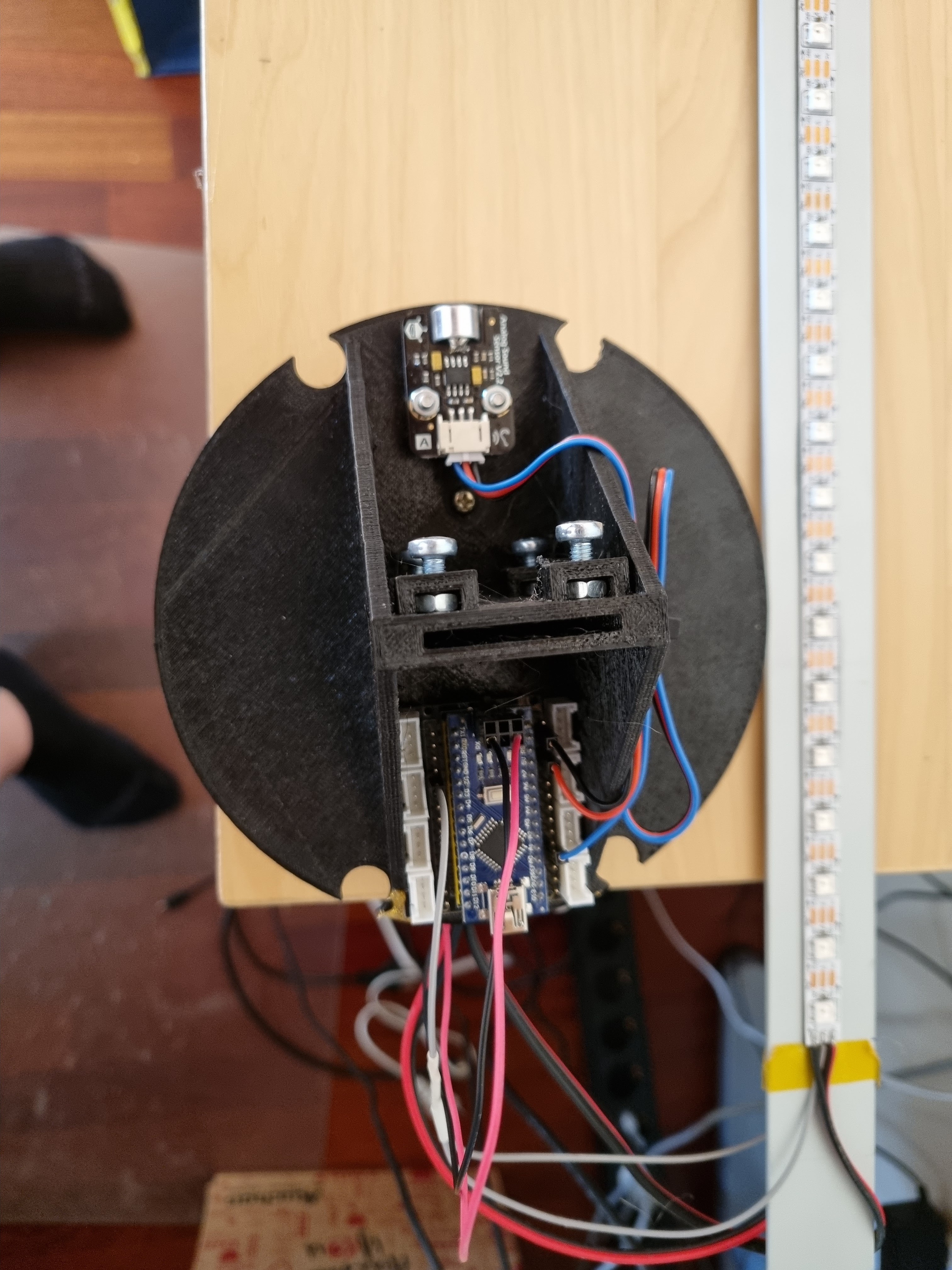
This project is just a simple, floor standing VU meter, using a microphone board, Arduino Nano, and WS2812 LED strip. Quite a simple one.

I had issues with the microphone board. I bought all together 7 different kind. It would be a long story the troubles I had with those (so not writing it today). Finally I choose one from DFRobot. Mainly because the two 3mm mounting holes, what perfectly fit into my design.

I don't want to write to much about it, so the pictures.

The finished "product" (first, just because it looks better when sharing on social media. 😂)


Bare electronics:

Assembled without the full enclosure:

How it is work (It is just her sisters yelling. I'm afraid, if I use some music on it, one of the YouTube's piracy dickheads ban it). It also has yellow and red, but unfortunately can't be seen on the video:

All of the elements (mainly code and the 3D design) can be found in this git repo. It also contains other VU meter related things, what is "work in progress" and not connected to this project:

https://gitlab.com/suf/suf-electronics-vu-meter

2023. március 20., hétfő

New Arrival 10. - Additions to my lab

There are many other things arrived since the last "new arrival" post, but today, I'd like to focus on the additions to my lab.

Agilent 53131A

Actually a few years ago I bought a 53181A Frequency Counter. Actually one of my former projects required a two channel counter, so it was itching in me, to get the bigger one.

For surprise my old 53181A had the high stability oven option. So now, I moved the OCXO reference to the new unit. I'll sell the 53181A finally (no, don't ask for the price, I've the buyer for it).

I finished the project were I think before, I need the analog multimeter, during the weekend - without it. Before that I scored this nice Hioki FET multimeter.


I don't know, if or when will I need it, but for ~$40 is nice addition to my lab (actually building some bench unit is still in my focus)

I still have one half junk PM3082 oscilloscope lying around. I didn't give up to repair it. There is no picture on the CRT. My suspect is the high voltage supply. Playing with the 16500V rail is not a child play.

I scored this for nuts, to achive the task (when I have time for it):


Fluke 80K-40 probe in carrying case. Good for 40kV.

Two additional equipment. Those are not yet arrived. Those are somewhere at the currier services

Bruster Digistant 6405

Yes, I have already a similar unit, but for GBP60, I can't leave it there.


Boonton 8201 Modulation Analyzer


No, I will not become an RF guy. Actually I've four Panasonic/Leaver VP-8193 units. I want to test, repair them (and finally sell three of it).
I read through the service manual. I have most of the required or similar test equipment mentioned in the manual (Audio Analyzer, Oscilloscope, Low frequency spectrum analyzer, multimeters, etc.)
The only missing piece was the Modulation Analyzer/Measuring Receiver. The manual mention HP 8901A/B or 8902A. Those units are going for insane price on the eBay.
I was thinking to try to simulate the function with my HackRF SDR, but I think the result will be questionable, and probably need some programming, what is time.
I was so fortunate to score this unit for the third of the cheapest HP 8901A. I think this one has the same, or better function, and optically looks much better, than any HP unit I seen online.