2016. március 30., szerda

AutomaTales - Rolling code receiver

[2016.04.16]: When I wrote this article didn't realized, that I used the old location of the cape manager slots file. Corrected.

When you sit in your car and try to enter to your garage, I know it is not fancy, but the most convenient device is the tiny remote you can hang on your keyring (something integrated into your car would be better and fancier, I may add something like this later on).

To be able to remote control the OpenHAB and the garage door/lights through it, I bought this rolling code receiver on the aliexpress:

http://www.aliexpress.com/item/RF-Rolling-Code-Decoding-Receiver-Module-2-Transmitters-DC-5V-4CH-TTL-Output-Learning-Momentary-Toggle/32295201884.html


My plan is to use it for switching the lights in the garage, control the garage doors and a few more (as it has two more buttons - exactly two) tasks.

First I put this onto a breadboard, powered up, and tried out if it works.

It was working for the first try, finding out the different channels for the buttons was easy like a child's play.

The only problem with the device, that it has 5V logic outputs and I want to connect to my BeagleBone Greens GPIO what isn't 5V safe.

I decided to use the simplest level shifter on earth possible. A resistor divider. A 39K and a 68K resistor does its job like champ, if you measure it with a multimeter.

The next part is to setup the GPIO on the BeagleBone. The OpenHAB uses the Linux GPIO Sysfs interface, what is supereasy to use (https://www.kernel.org/doc/Documentation/gpio/sysfs.txt).

First I tried to read the data from the command line. Connected one channel to the GPIO_60 (P9 pin 12) of the BBG.

On the console the following commands are needed:

echo '60' > /sys/class/gpio/export
echo 'in' > /sys/class/gpio/gpio60/direction

After this you can read the pin value by the following command:

cat /sys/class/gpio/gpio60/value

The commands went well, but doesn't matter if I push the button on the remote or not, always get back a 1.

Measured the input with a multimeter. It gives 1.6V even the pin of the receiver is on 0V. This means, that the BBG input pin is pulled up.
From this point I've two choice:

1. Switch of the pull up somehow
2. Use some active circuit as level shifter instead of the resistors.

I went for the first one.
Looked around and it clearly turned out, that changing the pull-up is not part of the linux GPIO framework. Read many things and found that BBG uses Cape Manager Overlays for this task. It was sometimes there, sometimes not, but on the 4.1.x kernel what I'm using is already part of the mainline kernel.

Here are some articles about it:

https://github.com/jadonk/validation-scripts/blob/master/test-capemgr/README.md
http://www.thing-printer.com/cape-manager-is-back-baby/
http://www.valvers.com/embedded-linux/beaglebone-black/step04-gpio/

The overlay repository (you can learn from it, but not necessary for the task here):
https://github.com/RobertCNelson/bb.org-overlays

The most useful of my findings was this online tool:

http://kilobaser.com/blog/2014-07-28-beaglebone-black-devicetreeoverlay-generator

It is able to create the overlay you need.

So for switching off the pull-up on Gpio 60 above you have to do the following things:

1. Save this file into the /lib/firmware under the name bspm_p9_12_2f-00A0.dts

/*
 * This is a template-generated file from BoneScript
 */

/dts-v1/;
/plugin/;

/{
    compatible = "ti,beaglebone", "ti,beaglebone-black";
    part_number = "BS_PINMODE_P9_12_0x2f";

    exclusive-use =
        "P9.12",
        "gpio1_28";

    fragment@0 {
        target = <&am33xx_pinmux>;
        __overlay__ {
            bs_pinmode_P9_12_0x2f: pinmux_bs_pinmode_P9_12_0x2f {
                pinctrl-single,pins = <0x078 0x2f>;
            };
        };
    };

    fragment@1 {
        target = <&ocp>;
        __overlay__ {
            bs_pinmode_P9_12_0x2f_pinmux {
                compatible = "bone-pinmux-helper";
                status = "okay";
                pinctrl-names = "default";
                pinctrl-0 = <&bs_pinmode_P9_12_0x2f>;
            };
        };
    };
};

2. Compile it:
dtc -O dtb -o /lib/firmware/bspm_P9_12_2f-00A0.dtbo -b 0 -@ /lib/firmware/bspm_P9_12_2f-00A0.dts

3. Load it:
echo bspm_P9_12_2f > /sys/devices/bone_capemgr.?/slots


echo bspm_P9_12_2f > /sys/devices/platform/bone_capemgr/slots

After this, the pull-up switched off. And I was able to read status of the remote.

Ok. Now it works for one channel, but what about four? I can generate four overlays, but how to combine them. I found very little information on it, until I found Adafruit's documentation:

https://learn.adafruit.com/introduction-to-the-beaglebone-black-device-tree/device-tree-overlays

Based on this, I was able to successfully combine the four generated overlays. Finally I used the P8 pins from 7 to 10.

The overlay (suf_keeloq-00A0.dts):

/*
 * SUF - 4-Channel Keyloq receiver cape
 */

/dts-v1/;
/plugin/;

/{
    compatible = "ti,beaglebone", "ti,beaglebone-black";
    part_number = "SUF-KEELOQ";

    exclusive-use =
        "P8.7",
        "P8.8",
        "P8.9",
        "P8.10",
        "mmc1_sdcd",
        "gpio2_3",
        "gpio2_5",
        "gpio2_4";

    fragment@0 {
        target = <&am33xx_pinmux>;
        __overlay__ {
            suf_keeloq_pins: pinmux_suf_keeloq_pins {
                pinctrl-single,pins = <
0x090 0x2f
0x094 0x2f
0x09c 0x2f
0x098 0x2f
>;
            };
        };
    };
    fragment@1 {
        target = <&ocp>;
        __overlay__ {
            suf_keeloq_pinmux {
                compatible = "bone-pinmux-helper";
                status = "okay";
                pinctrl-names = "default";
                pinctrl-0 = <&suf_keeloq_pins>;
            };
        };
    };
};

Compile and load:
dtc -O dtb -o /lib/firmware/suf_keeloq-00A0.dtbo -b 0 -@ /lib/firmware/suf_keeloq-00A0.dts 
echo suf_keeloq > /sys/devices/bone_capemgr.?/slots
echo suf_keeloq > /sys/devices/platform/bone_capemgr/slots

Now it works, but somehow it need to be loaded at boot.
To achieve this, you should add into the /boot/uEnv.txt:

cape_enable=bone_capemgr.enable_partno=suf_keeloq

NEXT: Integrating into the OpenHAB
2016. március 28., hétfő

AutomaTales - Install OpenHAB

Now here I install OpenHAB as the home automation controller, the brain of the whole system.
The OpenHAB is a java based system, so first we need an Oracle Java. To achieve this you have to add a PPA repository to the system:
BTW. I know that the sudo voodoo is absolutely necessary to keep the security. Even I'm working on my windows machine as a standard user and not admin since XP when the UAC wasn't even planed. But when I put together something on linux or windows and what I'm doing is clearly administrative task, I'm doing it as admin. So the first thing when I install several things, packages, etc. on linux I start with

sudo su

And don't bother to write sudo at beginning of every single line.

1. Add PPA repository of the Oracle Java and install it.

apt-get install software-properties-common
add-apt-repository ppa:webupd8team/java apt-get update apt-get install oracle-java8-installe 

2. Download OpenHAB files. You will need this ones:
https://bintray.com/artifact/download/openhab/bin/distribution-1.8.1-runtime.zip
https://bintray.com/artifact/download/openhab/bin/distribution-1.8.1-addons.zip
https://bintray.com/artifact/download/openhab/bin/distribution-1.8.1-demo.zip

Actually I usually download the files on my Windows machine and transfer them to the linux via WinSCP

3. Extract the files, create configuration

mkdir /opt/openhab
unzip distribution-1.8.1-runtime.zip -d /opt/openhab/ unzip distribution-1.8.1-demo.zip -d /opt/openhab/ cp /opt/openhab/openhab_default.cfg /opt/openhab/openhab.cfg

4. As we still in sudo mode we can start the OpenHAB server to test the functionality of our system:

/opt/openhab/start.sh

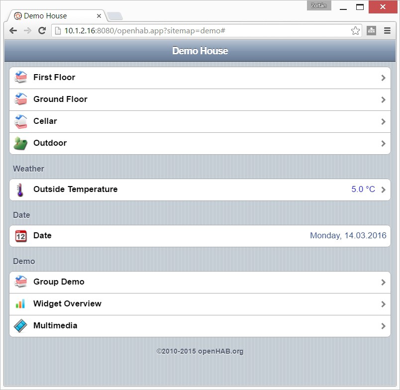
After waiting for a while, we can test in a browser if it works:

http://<ip address>:8080/openhab.app?sitemap=demo


OK. Our server works, but we not yet finished. Just stop it now.

First: you may realized that I didn't created any specific user for the openhab. There is a reason why.

The Ubuntu not really designed for embedded systems. Therefore no mechanism (what I'm aware of) for regular user to access GPIO (if you know a simple method for it please don't keep inside). On the next part I want to use GPIO. Based on this I plan to run OpenHAB as root.

Second: I need a method to run OpenHAB as daemon So..

5. Download the daemon script from here:

https://github.com/openhab/openhab/wiki/Samples-Tricks#how-to-configure-openhab-to-start-automatically-on-linux

Save as openhab into the /etc/init.d folder
Configure it:

chmod a+x /etc/init.d/openhab
update-rc.d openhab defaults

Edit the file with your favorite editor. Most probably you only need to change the RUN_AS from openhab to root
Start it:

/etc/init.d/openhab start

Now you can check it again if it still works via a web browser, and you can check the /var/log/openhab.log for errors.

2016. március 26., szombat

AutomaTales - Into my safety zone

Ok. So let start:

I'm not a linux guru. There are many favors of linux distribution, but I've just some experience with Ubuntu and Debian. In addition I usually not using any linux GUI.
So when I start a linux based project, it means to install an Ubuntu.
As I decided, this project will be based on a Beaglebone Green. Let start to install a 14.04 LTS to it.
The basic information reside here: http://elinux.org/BeagleBoardUbuntu

1. You need to download the image from here: https://rcn-ee.com/rootfs/2016-02-11/flasher/BBB-eMMC-flasher-ubuntu-14.04.3-console-armhf-2016-02-11-2gb.img.xz
(today the 16.04 image already exists, but I stick to the older as it seems more stable), download the image writing tool (Win32DiskImager): https://sourceforge.net/projects/win32diskimager/files/latest/download
And you need an empty minimum 2GB uSD card.

2. Expand the image to a folder in you machine. For example the 7-Zip will do it. Install the Win32DiskImager.
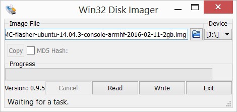
3. Write the image to a uSD card with the Win32DiskImager


4. When the writing is finished, insert the uSD card into the Beaglebone. Press and hold the boot select button (the one close to the uSD slot) while powering up the board. After short booting sequence you will see the "knight rider pattern" on the LEDs. Wait until it finish and the leds turn on.

5. Connect the board to the ethernet network. If you can figure out the address get by DHCP the steps from 6-8 are optional. Just reboot the board by power cycling it.

6. Install the PC driver for the board (if you have a BeagleBone Green, this is absolutelly necessary as you don't have HDMI connector to connect monitor). The windows driver can be downloaded from here:
64 bit: http://beagleboard.org/static/beaglebone/latest/Drivers/Windows/BONE_D64.exe
32 bit: http://beagleboard.org/static/beaglebone/latest/Drivers/Windows/BONE_DRV.exe
This is NOT a serial driver as you expect, but a virtual ethernet driver. You will need an SSH terminal to connect to Beaglebone.

7. Connect the Beaglebone to your PC. If it is was connected already, just cycle the power on it with removing and reconnecting the USB cable, when you disconnect the cable you can remove the uSD card, as you don't need it anymore.

8. If you run ipconfig on your machine a new ethernet interface will appear:


You'll get 192.168.7.1 as a new interface on your machine, the Beaglebone will appear on the 192.168.7.2. You can connect to it with an SSH terminal like PuTTY

9. If you didn't used the USB/Ethernet to log in, just login via the DHCP provided IP address. If you need static IP address edit the /etc/network/interfaces file and setup the address.

10. If you check the DNS settings of the system it is probably not working. Just by editing the /etc/resolv.conf will not resolve the problem, as it gets overwriten on the next reboot.

Edit the /etc/resolvconf/interface-order file and put eth* to the first on the list. This will give you the correct DNS settings.

11. Reboot the board.

12. Install the updates with:

apt-get update
apt-get upgrade

2016. március 25., péntek

AutomaTales - Why?

Why not?

I'm planning this since we bought our new house back in 2009. I wanted to have some automation right from the beginning. I've a friend who deeply involved in KNX systems. He said, that the cost would be around 10% of the house. I wasn't willing to pay such amount of money at that time, so I just drop the idea.
Of course some automation appeared here and there, but no integration between them.
I had a few attempt to the automation, but it didn't went further.
Just to collect them:
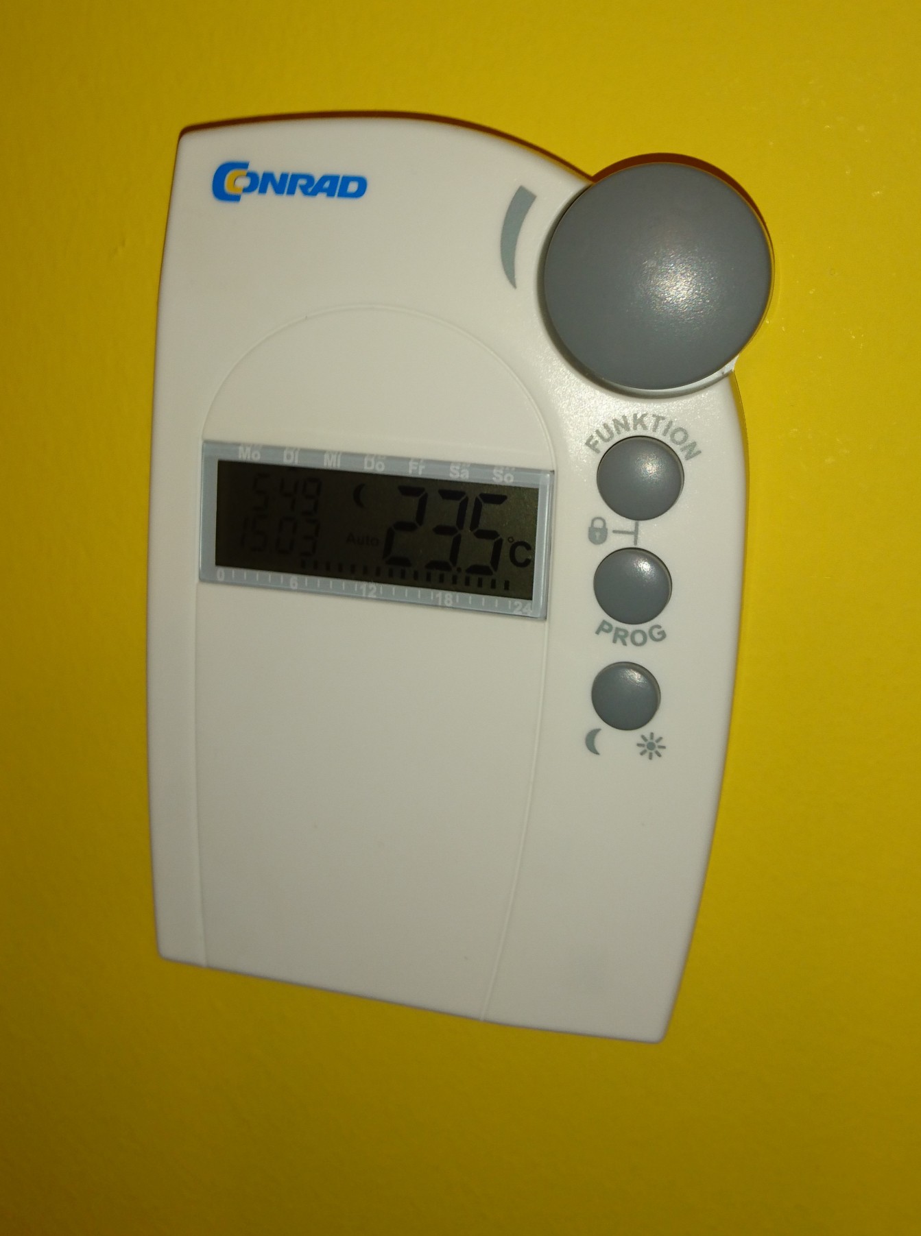
- Bought and installed few Conrad FHT80B thermostats and connecting valves. These are working today as "islands" in the house.


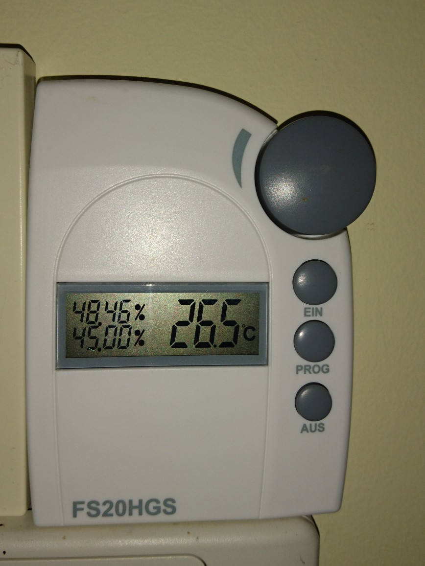
- Bought and installed a humidity sensor and switch (part of the Conrad FS20 system) for controlling my dehumidifier (the integrated control was a heap of crap)


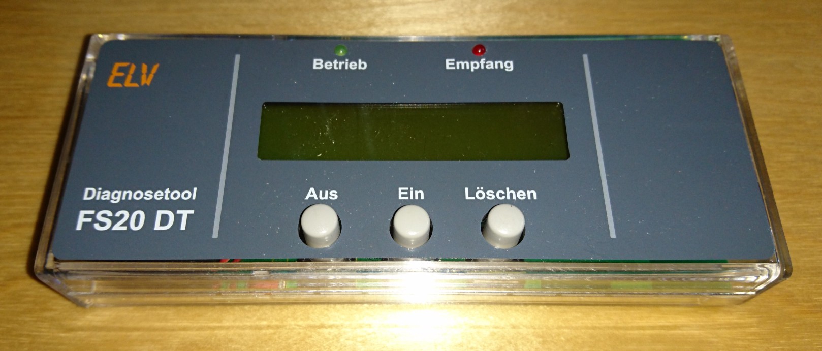
- Bought the computer interface and the code monitor for the FS20 system. The interface is still in a box. The code monitor (or call it debuger) was used a few times


- Bought the CUL v3.2 for controlling the FS20 but kept in one of my parts boxes until now.


- Designed and built a few thermometers, what was planned to be a base project for a future thermostat project what never happened.


As you see almost nothing happened until now.

Why now?
As I'm progressing with my electronics projects, it got some attention from my wife. Attention means task here.
In our garage you can't see anything if you don't switch on the light, but you can't switch it of after you get into the car. The result: if I'm lazy (sometimes I'm) the light left open.
The task: resolve this issue.
It would be a simple solution, to change the switch to a momentary button and add a timer, but....
I want to create a home automation system. This is a good starting point. So rather a simple solution, why not start to build a big one? :-)