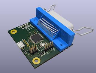
This is a small upgrade, bug fix of my previous ATMEGA32U4 based USB-GPIB interface. The previous had some flows. It had collision between the bootloader LED handling and the GPIB signals. Completely mixed up the original Arduino signals to be able to use the interrupt handling of the processor. Also used a full 8 bit port for the data bus to be able to read/write once and not bit by bit.
- For this version I chose a bit different view:
- Try to stick to the original Arduino Leonardo pin configuration as much as I can
- Give up the interrupt handling except for SRQ line
- Kept the 8 bit data bus
- Made it configurable - you can choose between the pin config used by the AR488 project and the 8 bit data bus above (the AR488 version doesn't need custom bootloader)
- Keep the capability of the using the activity LEDs
- Added serial debug port
Later this design will be based on this adding the proper GPIB line drivers. This design is only capable to drive one instrument (maybe good for more, but I rather not try).
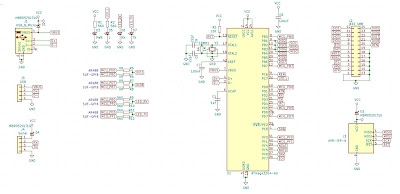
The schematic:
The "exploded" 3D model:
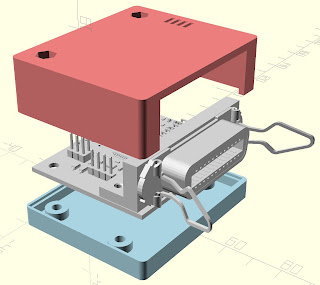
Yes I know that the gender of the connector is not the correct on (but who knows today, what gender is appropriate), but I didn't find 3D model of it and It wasn't so important, just to represent the size for model design.
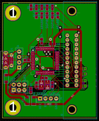
Here you can find the complete design:
With this design the number of finished designs in the group is rise to two so here is the time to order the PCBs.
Nincsenek megjegyzések:
Megjegyzés küldése