A következő címkéjű bejegyzések mutatása: GP-IB. Összes bejegyzés megjelenítése

2022. február 19., szombat

Measurement Control - Direction 2.

There are lots (or you can call nothing) happened since the last post regarding my measurement control application.

Name

I didn't like the random names I gave to this solution (Control software, interface, anything). Didn't look and feel professional. Finally I found a name for it: MeasureFlow

Registered a domain for it:

measureflow.org

(nothing there yet)

A github and a gitlab group:

https://github.com/MeasureFlow

https://gitlab.com/MeasureFlow

Software

I have the direction (partially). The software was plug-in based, but not other ways modular. I decided to architecturally separate the application to frontend and backend. The backend will be dotnet 6 based minimal REST API. The frontend is still question.

Started to write the backend. As the codebase doesn't need too much porting until we just talking about the instrument continuous measurement and not a complex workflow. So it is almost working (just didn't try out the last pieces yet)

Hardware

The ordered PCBs arrived (both the USB-GPIB and the USB-RS232). I was so fortunate in this chip demanding times to find 10 ATMEGA32U4 locally.
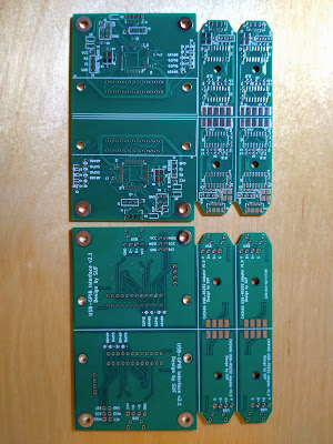

I didn't find the time yet to solder and test. Anyway it need firmware, so it is useless until I resolve the firmware related questions.

Firmware

We arrived to the point, what cause most of the troubles to me in this whole picture.

During the last week, in my free time I mostly tried to understand the USBTMC based implementation I found online. I didn't become a big fan of it. No proper reusable implementation of the USBTMC interface what corelate to the LUFA design principles. It is based on a not finished, so fuzzy LUFA demo, bad handling of the AVR pins, weird off interface configuration handling.

Tried to understand, how it is work, how can I port to my hardware. Originally I just wanted to exchange the pin layout for my own hardware design, but I know now, I can't stop there.

Last Sunday then I finally realized the biggest problem I have with this whole thing. What I found was shocking to me. Root of the problems is not the implementation, but the standard itself.

The standardizing board was thinking completely differently than myself.

Their intention: create a solution on instrument side what able to wrap the existing GPIB interface while moving the development to the native USBTMC interface

My intention is to create a device what can sit between the USB and several GPIB based devices, handle sub addresses also.

At first read you may not find too much difference between this two. The difference is that the standard doesn't contains anything to address the GPIB devices. It presume that the USBTMC device with USB488 extension connected to the USB port is a single instrument and not many of it.

If I would just deal with instruments without GPIB sub addresses, I would may live with this, but unfortunately this is not the case. I've VXI mainframes, Power mainframe with GPIB sub addressing.

Even if I dig further neither HP (Agilent/Keysight) nor National Instruments who manufacture USB-GPIB interfaces use USBTMC with USB488 extension in their devices (HP 82357B, NI GPIB-USB-HS). They use standard base device USB ID or vendor specific. Those are proprietary.

Back to my unit. Here I should decide, what direction should I chose while developing the firmware of my adapter. Here are a few possible path I can think of:

  1. Resume working on my USB-CDC implementation (based on Prologix command set). It has drawbacks like CDC is slower than the USB native bulk endpoints, on the host side I need to port my own driver to the MeasureFlow software, will not be compatible almost any of the existing host side software stacks.
  2. Use AR488 firmware. In addition to all of the drawbacks above, I need to implement the subaddressing (or secondary addressing), in their codebase as it still not implemented yet.
  3. Mimic HP or NI interface. This is problematic from various standpoints. Lots of USB sniffing, possible copyright issues, etc.
  4. Develop a USB composite device - check with poc if Keysight IO library supports this. The concept is to have one CDC device used as control channel (manual device setup, SCPI emulation, etc.). Generate dynamic USBTMC device for each GPIB device (primary and secondary address) based on automatic device discovery or manual setup.
Currently it looks like that the last one is the target, if I not run into unresolvable issues.

2021. december 5., vasárnap

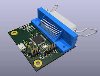
USB-GPIB Interface v2.1


This is a small upgrade, bug fix of my previous ATMEGA32U4 based USB-GPIB interface. The previous had some flows. It had collision between the bootloader LED handling and the GPIB signals. Completely mixed up the original Arduino signals to be able to use the interrupt handling of the processor. Also used a full 8 bit port for the data bus to be able to read/write once and not bit by bit.

  • For this version I chose a bit different view:
  • Try to stick to the original Arduino Leonardo pin configuration as much as I can
  • Give up the interrupt handling except for SRQ line
  • Kept the 8 bit data bus
  • Made it configurable - you can choose between the pin config used by the AR488 project and the 8 bit data bus above (the AR488 version doesn't need custom bootloader)
  • Keep the capability of the using the activity LEDs
  • Added serial debug port

Later this design will be based on this adding the proper GPIB line drivers. This design is only capable to drive one instrument (maybe good for more, but I rather not try).

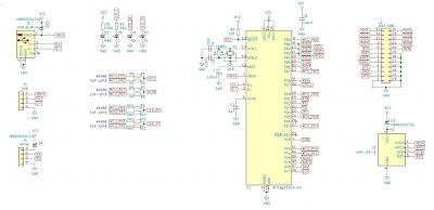
The schematic:

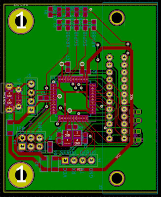
The PCB design:


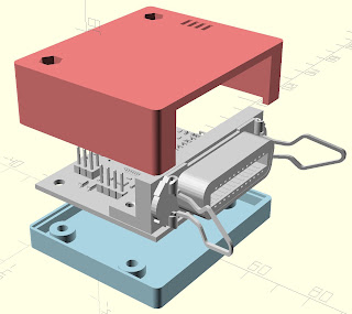
The "exploded" 3D model:


Yes I know that the gender of the connector is not the correct on (but who knows today, what gender is appropriate), but I didn't find 3D model of it and It wasn't so important, just to represent the size for model design.
Here you can find the complete design:
With this design the number of finished designs in the group is rise to two so here is the time to order the PCBs.


2021. november 27., szombat

Measurement Control - reboot

Preface

In the recent years I put substantial amount of work in controlling my various instruments from computer. The goal is to achieve some added values, like logging, better visibility, more functions, etc.
Looks like I a bit failed with this, as none of the things reached the usability state.
Even I put aside the thing months ago. Now I feel the need to restart the project and achieve some "working" result.

Plans

Reorganize the source repositories

This is needed as I learned many things in the recent years from my work on git (branching strategies, release management, etc.)

Create an USB-RS232 interface

I've a few devices using RS232 interface instead of (or on the side of) GPIB. Yes you can buy USB-Serial interfaces for nuts. Why you need another? Most of the things you can buy has no proper signal levels. They use TTL levels instead of RS232 levels. Most of the professional instruments require proper levels. The interfaces with proper signal levels are not cheap or you risk buying something on Aliexpress what states it correct, when not.

Redesign USB-GPIB hardware

My ATMEGA32U4 based interface working perfectly. In the recent years I realized a few things regarding to it, what feels like some adjustments are needed:
  • Create a physical design what can be mounted a 3D printed enclosure
  • Abandon the unnecessary connectors added for future improvements like display, additional device control, etc.
  • Add serial debugging capability (according to AR488)
  • Maintain bootloader compatibility with Arduino Leonardo
  • Also keep the advantage of using a complete 8bit bus of the MCU for data transfer (require modified bootloader
  • Maintain software compatibility with AR488 (https://github.com/Twilight-Logic/AR488)
  • Add activity LEDs (the original Arduino Leonardo has those)
  • Proper GPIB interfacing with TI chips (in a different HW version)
Maintaining AR488 compatibility doesn't mean I intend to drop the development of my own firmware. I still not a fan of the 3000+ lines of code in a single source file and the AR488 still doesn't support GPIB subaddressing. I've several instruments (VXI mainframes, power supply mainframe), what require subaddressing. On the other side it has device mode, TI GPIB chips support, what is missing from mine and support from software like sigrok.

Proper bootloader for USB-GPIB

I created a bootloader for the the v2.0 of my board. This was a result of an incident caused by reusing the USB activity LEDs of the Arduino Leonardo, killing my GPIB communication. The issue was resolved then, but the result is poorly documented (https://pakahuszar.blogspot.com/2020/04/gp-ib-5-v20-board.html), hard to reproduce and killing the activity LEDs instead of relocating them.
Now I'm trying to create a maintainable buildable, and properly installable solution. Also want to allocate a proper PID/VID from pid.codes

Power supply control software

My virtual instrument software is able to do many things but I realized it is too much for the first iteration.
There are many things already achieved with it, but for the reboot I want to have more realistic goal. So using the plugable driver support from it, I want to just create a power supply control software for my many supplies (even the HP 66000A mainframe is useless without software control as I don't have keyboard for it). I don't want to add higher functions yet.

Further...

Sure, I don't want to stop here, I want to reboot the virtual instrument software, my curve tracer, etc.
But those are cloudy right now, and if I lose my focus on it, this project tsunami will be shelved. Again.

2020. szeptember 9., szerda

Instrument Control 1. - The Beginning

 Convergence.

This is the word what pop into my mind when I think about this project.

I feel this is the point where my lab building, instrument collection, instrument/interface building and measurement efforts connected together, giving me some higher level capabilities, than the things what I have on hand.

Where this is started?

I was building audio equipment in my childhood. Later when I restarted this hobby, was the plan, to continue to work audio electronics. I was lack of test equipment (had just a dying DMM). I wanted to build instead of buying. This lead me to the digital electronics.

Later I bought lots of equipment. At a point of time, I bought a HP 8903B Audio Analyzer, to be able to draw various graphs on amplifier performance. But the problem is, connecting an XY recorder is an outdated solution. For connecting to a computer, you need an interface. I wasn't happy with the readily available GP-IB interfaces, so my GP-IB interface is born.

Later, I was looking into the available controller software for the HP 8903B, and didn't like it. In addition, I wanted to connect/control my other instrument to a PC, having more ideas than just controlling the audo analyzer. So after a few control experiment, my "Virtual Instrument" project is born.

After two years, with many struggling, restarting and redesign, it looks like the system started to work.

The concept:

I wanted to create something flexible, while it able to use without programming skills. I wanted something can be used for serious measurements, can be used with many of the instruments I have. Compatible with several communication interface types. The whole system need to be use plugins for the future development.

I created a few object types  

Controller:

Something run the show. Starting the measurement series, even providing some base data for the instruments. Currently I implemented these:

- Continuous controller: Just runs the measurements one after the other. This is the usual work scheme most of the instruments, like multimeters.

- Single shot controller: Just run one measurement, then stops

- Variable controller: Can be setup for a series of measurements. It provide a linear or logarithmic dataset. It is originally created with the HP8903 in my mind. In the first trials I used it as a logarithmic frequency source for the integrated sine wave generator

Instrument:

Some device (typically hardware), can measure something. Can consume measurement results from the previous instruments (or controller) in the chain and/or provide measurement results for the next object.

Currently two type of instruments created: HP8903 Audio Analyzer, HP3478A 5,5 digit DMM

The instruments always working in single shot triggering mode. The reason: The controllers above are running the show and not the instrument's internal controller.

Filter:

It is originally designed for filtering, running maths, converting the results. During the development I realized, that similar functions are needed between the instruments also. So I realized that keeping filter plugins separately from the instruments has no added value.

I'll drop the filter functionality and create the filters as instruments.

Target:

Something can display or save the measured results. Currently two target available:

- Digital Display: can display the currently measured data, also provide min, max and average displays, with variable number of digits displayed

- Chart Display: Capable of displaying the measured data in a chart, using multiple series of data, using linear or logarithmic axes (this is not completely ready)

Connections:

Not part of the measurement chain. It is used by the instruments as communication interface. Currently available:

- AvrGPIB - My own GPIB board (on the development I wrote a few articles)

- IVI VISA - The standard instrument interface. I tried it with the Keysight stack and a Keysight USB/GPIB interface. Actually it was quite unstable, so future development is needed

- Serial - It is implemented and not. Actually it is used by the AvrGPIB, but I never tested directly, so it can have problems

So, this is what I have right now. I tested with the HP 3478A:

And later with the HP 8903B:

It is just AC Level measurement, the input directly connected to the output with 20-20000Hz sweep, 1V AC. Actually you can see some error:

Later with some modifications on the graph (still not finalized):

You can see around 2% error. So the instrument need some repair (at least replace of the filter caps).

So I intend to continue the development, adding support for other instruments and I have many improvement idea.

The code is written in C#.Net with Visual Studio 2019. The repository is located here: 

https://gitlab.com/suf/suf-electronics-VirtualInstrument

Anybody like this project, have spare time, some programming knowledge, and willing to help in the development effort, wellcome.


2020. április 25., szombat

GP-IB 5. - V2.0 Board

When I wrote the previous part of this post, one of my friends complained, that was to short. I can promise. The current one will not be.

Prelude
I already have several GPIB boards on my desk. Actually I have 1.0, 1.1 (and now 2.0) version of my board. One of the 1.0 boards doesn't work correctly. I meant, I need some diagnostics into the firmware to track down the problem. So I wrote a diagnostics extension to the current instruction set. It is able to manipulate the GPIB pins directly (I tried to resolve the error of this board, but the results were inconclusive).

v2.0 Board
To step forward, I soldered in the next generation board. It also need some software modification as it use ATMEGA32U4 instead of the ATMEGA328P on the previous one.


Everything went easy. Too easy.
The ISP programming was successful immediately. The software modifications took less than five minutes. The board upload worked, just right after fixing one single easy to handle bug.
Connected to my test HP3478A multimeter. Run a scan command. It immediately found the instrument and reported back the reading. The only gotcha was the reading characters appeared one by one slowly.

Next day - troubleshoot
I was thinking one unsoldered pin, and reading timeout cause the problem.
Fired up the diag mode, and realized that the D1, IFC, SRQ and ATN always reporting back high logical level, whatever I do.
Tracking down the issue - playing with the other boards - just came out, that the diag mode doesn't handle certain pins correctly. Modified the diag mode. It resolved the issues on the 1.0 and 1.1 boards, but not on this one. The D1 and the ATN issue remained.
Later on, somehow I figured out that those are used on the Arduino Leonardo board (what I was using as configuration and the bootloader of it) as RX and TX LEDs for the USB communication. Holly shit.

Redesign or fight?
The dilemma came here. I've two options:
Either I redesign the board, and send to manufacturing once more, or fight with the Ardunio bootloader, core, whatever. I chose to fight. Reasons:

  • Design and manufacturing has costs, and need several days (or even weeks) until the new board arrive
  • The ATMEGA32U4 has two externally accessible full 8 bit ports. Those can be used for faster communication with direct port manipulation. Unfortunately those LEDs are use one pin of each of this ports. So if I don't use them, I lose the speed here.
  • Digging deep is fun. I can learn a lot from it.


Blame the bootloader
Actually I don't know why, maybe I read something on a forum, I was thinking, I need to modify the bootloader, and it will resolve the problem (maybe the serial use it for the communication, I don't know)

New bootloader
First of all Identified the source code of the bootloader. It is located here (https://github.com/arduino/ArduinoCore-avr/tree/master/bootloaders/caterina). Checked the Makefile it also need a library called LUFA for the USB communication. I also checked this out. Added the latest Win64 compatible avr-gcc and make.
I tried various ways to point the Makefile to the LUFA, all of my attempts failed. Also it missed grep tool. I felt like the Windows is a dead-end for this build.

Switch to Linux
Didn't wanted to build a linux machine, or add a Hyper-V based Linux. So I fired up the Subsystem for Linux and installed the Ubuntu 18.04LTS from the Microsoft Store.
Installed avr-gcc, build tools, make, etc. on it.
Found the filesystem location of the Ubuntu in the Windows filesystem and copied the source code over.
It wasn't work. I got various permission issues with the copied files, so I gave up and cloned the repos once more.
Trying to compile gave the same errors as on Windows without the grep problem. After several path modifications, adding the USB VID and PID finally it started the build. The result was a catastropy:


The bootloader in question was built last time 8 years ago. Both the avr-gcc and the LUFA library stepped forward since.
Figured out what tag was used originally, switched the repo to it. Now the bootloader compiled successfully.

Testing with the new bootloader
I didn't wamt to hack it into the Arduino IDE so I flashed the bootloader manually to my board. Uploaded the code also. And....

and it failed.

Hack the core?
No. Even I figured out that the problem is probably in the USBCore.c, I didn't wanted to hack it. It wouldn't create a future proof solution.
Looking around and thinking lead me to create a custom Arduino board specification for my project.

New board config - not yet
First of all I wanted to have something I can learn from. I found an ATMEGA32U4 based custom board from ArachnidLabs (http://www.arachnidlabs.com/tsunami/), and the git repository for it: https://github.com/arachnidlabs/arachnidlabs-boards
It turned out immediately that I need a stable place to to host the json and the package zip. Something I can count on that will be there for a while. Something can be accessed without any authentication voodoo (like OneDrive).
As the AVR-GPIB project of mine hosted on GitLab, I was looking around there. As Github has Github pages, what a surprise, GitLab has GitLab pages.
I read through the documentation, it was still not clear, how to setup the GitLab pages.
Created a repo named suf.gitlab.io, put the files in there. Nothing happened.
Ok, it looks like I need a gitlab-ci.yml for building the site. This isn't surprising concept to me, as in the last few years I'm working as DevOps engineer. Writing Jenkins CI/CD pipeline scripts on daily bases.
Wrote the script, pushed the repo, failed. Some naming wrong. Corrected.
Next. Building correctly. The site still give 404 back.
After many tries realized, that my files from the GPIB subdirectory landed into the root of the site. I was thinking that it is because the root has no files in it, just the GPIB folder. So added an index.html.
The previously successful build failed again.
After reading many things, several trials, came out, that the only approach what is working, to add everything to a newly created temporary folder and rename (mv) it to public, what is the designated name of the publishing.
So my GitLab pages site born: https://suf.gitlab.io
It is small, it is yellow, it is sour, but ours (I know it is not got through in English, as it refers to an epic Hungarian movie from '69 - https://en.wikipedia.org/wiki/The_Witness_(1969_Hungarian_film)).

New board config - now really
Created the json, modified the pins_arduino.h (pointing the LEDs to two not externally exposed MCU pins), built the package, created the hash, added into the json, uploaded the whole thing to the GitLab, added the json to the Arduino IDE, went to the board manager and...
nothing happened.
Repaired two things looked like bug: name of the json. I don't know if it is a requirement, or just a kept convention, but renaming don't harm.
Realized, that I didn't change the length of the package file in the json, so now I did it.
Push to GitLab, back to Arduino, my config appeared in the Board Manager
Install: failed. There must be a single folder inside the package.zip.
Changed the required things, push to GitLab. Install now works.
Try to upload the code I wrote.
Getting weird inconclusive errors, communication problems. Switched back to Arduino Leonardo, getting the same errors. It smelled like problems with the Windows COM handling. Reboot resolved it.
Try to upload once more. There are missing avrdude parameters. Various parameter related issues. Finally I added into the package.txt whatever I found. It looks like that the ArachnidLabs config was written for an earlier Arduino IDE what doesn't require those parameters.
Now the board upload works.

Try it out
GP-IB diag functions now work as I expected. We are ready!!!!
Noooooo.
The diag works, the communication with the instruments, not. Enough! Sleep!

Next day
It was something itching in my mind. Tried out the previously working boards. Stopped working those too.
Either my HP 3478A multimeter died, what I'm using for the tests, or the diag modifications what I did in the code later on, disrupted the communication.
Figured out soon: the diag was buggy. Fixed it. Now the v2.0 board works.

End of this story.
Will continue with the further hardware and software development of the GPIB adapter.

2020. április 14., kedd

GP-IB 4.

Nine month. Today exactly nine month ago written last about my GP-IB adapter (http://pakahuszar.blogspot.com/2019/07/gp-ib-3.html). Its been a hard delivery.
I'm announcing proudly the birth of the working GP-IB interface software. It still need to learn and grow. Things are missing from its skills like device mode and USBTMC capability.
Both the father:


The mother:


And the child:
https://gitlab.com/suf/suf-electronics-gpib

In good shape:


And waiting for a long and prosper life.