A következő címkéjű bejegyzések mutatása: SMPS. Összes bejegyzés megjelenítése

2021. október 15., péntek

Gigabyte and modular power supplies

On the side of the CNC router project (as always) I started an other one. This is clearly just a PC project. Build a NAS from the things I have on hand (ceiling cleanup 😂).

During the long years, I used several - called modular - ATX power supplies. Those things allow you to clean up the cable jungle a bit, what always shown up inside the PC cases, by allowing you to detach unnecessary cables from the PSU. These are the peripheral cables used for the mass storage, graphics cards, etc.

The connectors on the supplies for the modular PSUs are not standardized, usually use the same kind of connector (2 row, 6 or 8 pin, Molex Mini-Fit).

Yes, I bought PSUs from different vendors (Gigabyte, Chieftec, etc.). Yes, I never labeled the cables. And yes, I keep those in one box. This means, I don't have a clue, which cable belong to which PSU.

For the NAS PSU I needed several cables (in hot swap bays, I plan to use 14 disks). If I mix those up, I can imagine the firework it can cause.

The subject currently is a 550W Gigabyte Odin (I also have an 800W somewhere just not found in the ceiling yet). I downloaded the manual of it. It has the connector pinout in question. (Indicated, not to use it as is bad)
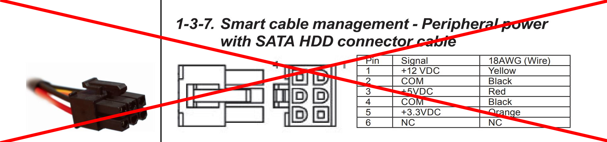
I started to starch my head. None of the cables in the box has this pinout.

DMM on. Measure.

My suspicion become true. The manual is garbage.

This is the correct pinout (the connector drawing is from Molex and show the connector on the PSU itself), and it correspond to all of the cables in my box (it is maybe a coincidence, but Gigabyte, and Chieftec use the same pinout):


2015. június 7., vasárnap

USB Booster 0. - :-)

A few month ago I started a project called USB Booster. It doesn't hit this blog as I had not enough time to write about it here. It is just started on the Hackaday.io.
The problem:
I've a huge amount of various development boards. These boards almost exclusively powered from USB. It is just happened that I've no powered USB hub (I even tried to buy one, but the one I was coosing, wont fit into my needs).
Some of the boards really require the 5V. If you measure the voltage on the USB - hubs, cables included, with a load of a high power dev board (like STM32F429-DISCOVERY), it could fall to 4V or even lower. It happend to not enough to this board. The application USB wasn't working.


The solution:
It pop into my mind, what if I just put a switch mode boost converter into the USB power line, and allow the data lines to connect to the board?
It is a simple dongle put between two USB cables, no external supply needed and done.
I was thinking to build it with the common MC34063, because it is easy and cheap. Later I realized, that the result will not be cheap because the big external components (low switching frequency), and in addition it be big and inefficient. So I dropped it.
The project kept in this state for months.
A few weeks ago I was searching for a cheap boost converter for an other project. Suddenly I found Microchip MCP1642. It turned out, that it is not suitable to that project, but nicely fits into this.
So the story begin here...