No. This is not the sane animal I wrote about in my last post. It is a different unit with a different function.
Ok. Start at the beginning.
I bought 47 Ronin unknown transformer. Wrote about it here: https://pakahuszar.blogspot.com/2022/04/new-arrivals-5.html
Started to play with those. Made some measurements:

It is clearly an SPMS transformer. It has 4:1 turn ratio (I guess it is from some kind of 48V supply. Maybe a PoE supply?), and ideally around 100kHz working frequency.
To test it further, I need to add some load to it.
And the problem starts here. My signal generator is not up to the task. So I need something for testing.
When I see such kind of requirement in front of me, I usually thinking further. I want something can be used for future tasks also.
It would be nice to have the following features:
- Few tens of volts output (ideally 650Vpp - I'll be far from it, see later)
- 5A maximum load on low voltages
- DC - 1MHz bandwidth (100kHz was enough now, but for the later definitely i will need more)
- Variable gain. Let see up to 40dB
First, look around, what is available on the market:
Keysight 33502A (https://www.keysight.com/us/en/product/33502A/isolated-amplifier-2-channel-50-vpp.html)
Are you lost your mind? >$3500 for a bloody amplifier???
Rigol PA1011
Nice little fellow. Bit simple, but almost good enough. The ~$400 price tag, still too high
Siglent SPA1010
Same true what I wrote for the Rigol
Juntek DPA-2698
It is a real, born on Aliexpress unit. It has $89 price tag, what is acceptable. I'm just not happy with the 0.5A output power (it use two TI BUF634 diamond buffers - the diamond buffer will resurface later in this post)
Looked around on the DIY space. It looks like, this is not a widely required thing, so I only found two projects (the second one is based on the first, just added some extra circuitry on the PSU side)
https://www.dmcinfo.com/latest-thinking/blog/id/9462/low-cost-function-generator-amplifier-diy
The OPA541 would be a nice candidate, but at the end of the day, I didn't like this project, had problems with the bandwidth, etc.
Finally I decided to build/design something from starch. Actually found a circuit, in an application note. It is an operation amplifier extended with a diamond buffer designed by Jim Williams: https://www.analog.com/media/en/technical-documentation/application-notes/an47fa.pdf
The circuit in question on page 45-46 (Figure 101)
With changed semiconductor set and adjusted values, I intend to achieve 24Vpp output at 5A.
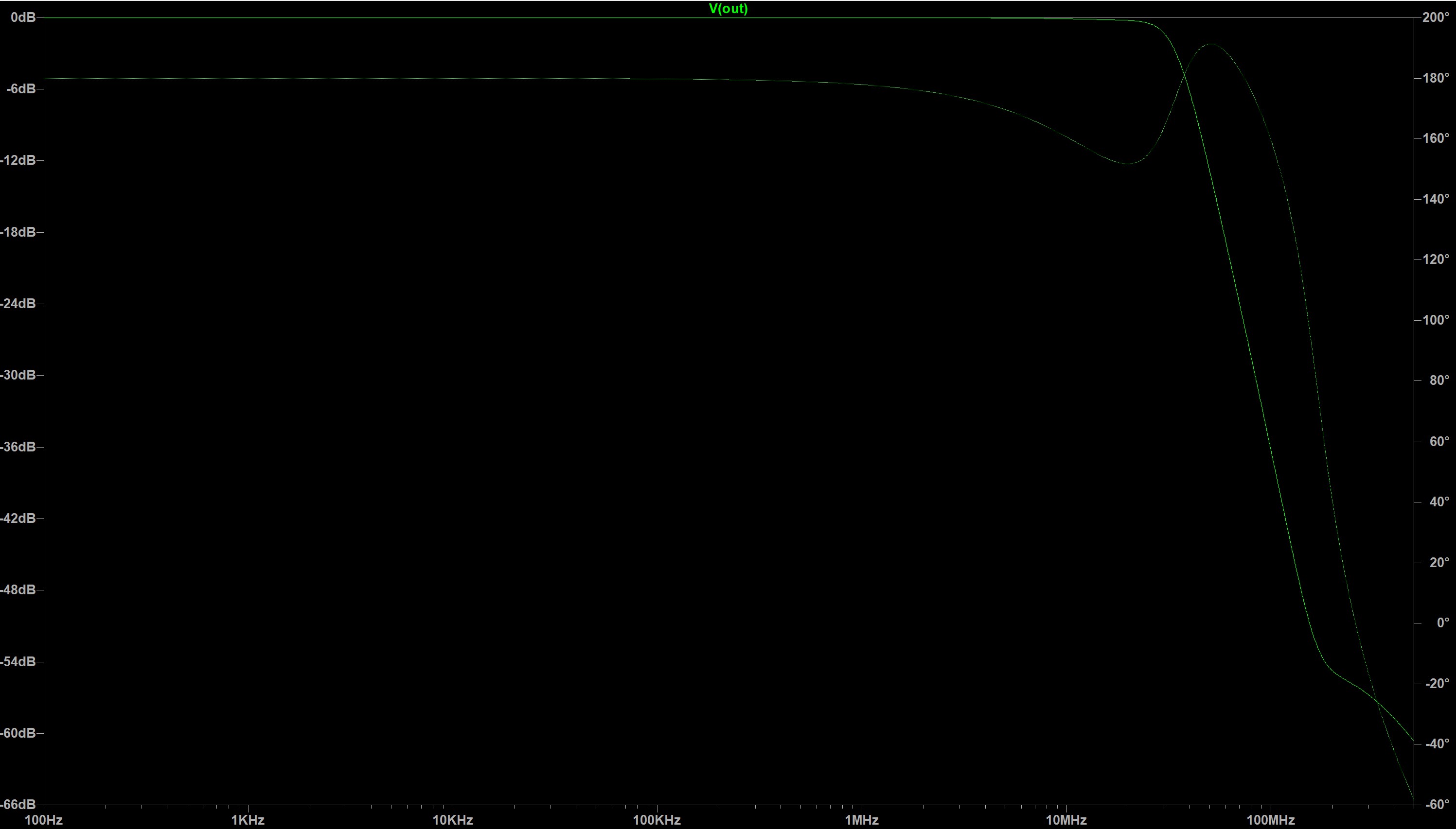
I run some simulations on it. Even with 40dB gain (two stage), I was able to easily achieve the targeted 1MHz bandwidth. I'm still not a real analog guy, so I don't yet know, if the whole concept will work. Here is the simulated (single stage) circuit with 0dB gain:

Added some digital control circuitry for it, and designed a PCB for it.
The control allows me to change the gain from 0 to 40dB in 5dB steps, and switch between AC/DC coupling at the input. I also added placeholder for capacitors, every place to able to handle the stability, if needed.


Now I just ordered the parts and the PCB for this power amplifier section. I still have a few addition in my head for this instrument, but I'll just build the amplifier itself, to check the performance. The other things come later:
- Power supply for the analog parts (+-15V/300W)
- Power supply for the digital parts (+5V, +12V), and fan controller for the cooling fans (Amp, Analog PSU)
- TrueRMS converter, automatic range switch, ADC - for measuring voltage/current on the output
- Control processor board
- Front panel (LED display, buttons, rotary encoder, or just using a small TFT originally made for 3D printers)
Yes, maybe I overthink, overcomplicate things 😁
Nincsenek megjegyzések:
Megjegyzés küldése