After my CNC stopped, measured a quick one, for deciding if the motor or the power supply is the guilty one.
It was the motor.
This means I've to face my largest fear regarding the CNC. The motor holder and the whole z-axis moving parts are manufactured from a single piece of metal. The motor was so tight in it that I cant remove it without much force (I tried already). I fear if I try to strain it to hard, it will broke.
Finally I was searching a wooden wedge in my workshop, removed the two screws, stave the wedge into the holder and with some force I was able to remove the motor.
Here is the guilty:
I ordered quickly a new one - this time a 400W one - from the eBay. Until it arrives I put the CNC aside. But it is possible that I tear down the motor to see what is the problem.
2014. július 30., szerda
2014. július 28., hétfő
SG90 servo controller
If I'm finally able to reconstruct my 3D printer (I haven't touched it for a while) I want to have an automatic bed leveler on it, because the bed leveling today is painful. I found a solution what I like: https://www.thingiverse.com/thing:301715
For this I ordered a fistful of SG90 servos from the eBay what already arrived for a while.
At the end of the last week a task come by. It should be solved to change the vertical angle of a small webcam, what is in a not easily accessible place. I had only the weekend for it because I wanted to finish until today.
The original idea was the following:
TI Launchpad + SG90 servo, connected to a PC via USB port and it can be controlled from there.
I found a small sample code on the net:
https://www.youtube.com/watch?v=b0SYQ7JHgt4
It was working, but I didn't liked it. I was trying to write something based on the datasheet. The code was not working. The timing on the datasheet had no connection to the reality.
Finally I totally rewrote what I originally found. Restructured it just kept the timing.
After this the serial communication come.
After a bit struggling become clear that the user serial function of the LanuchPad is not even close to a working thing under Windows 8.1. The driver is there. It even allows me to connect, just no communication in the terminal emulator.
I picked from my drawer a CP2102 board from the Conrad. After some driver collection, it started instantly. I finalized the code, everything works, just I can't leave the it mechanically in this shape.
Unfortunately drawing schematics, designing and manufacturing PCB was out of question, because of the time. Only the perfboardleft as option (ohh, how I hate it).
Here is the result:
I'll put the finished code out to the GitHub.
Unfortunately I was not able to finish the whole project. When I tried to mill the camera holder on the CNC the spindle stopped and didn't started anymore. For the time being I had no energy to take it apart to find out, if the spindle or the shiny new PSU is the cause. I'll measure around tomorrow morning to find it out.
For this I ordered a fistful of SG90 servos from the eBay what already arrived for a while.
At the end of the last week a task come by. It should be solved to change the vertical angle of a small webcam, what is in a not easily accessible place. I had only the weekend for it because I wanted to finish until today.
The original idea was the following:
TI Launchpad + SG90 servo, connected to a PC via USB port and it can be controlled from there.
I found a small sample code on the net:
https://www.youtube.com/watch?v=b0SYQ7JHgt4
It was working, but I didn't liked it. I was trying to write something based on the datasheet. The code was not working. The timing on the datasheet had no connection to the reality.
Finally I totally rewrote what I originally found. Restructured it just kept the timing.
After this the serial communication come.
After a bit struggling become clear that the user serial function of the LanuchPad is not even close to a working thing under Windows 8.1. The driver is there. It even allows me to connect, just no communication in the terminal emulator.
I picked from my drawer a CP2102 board from the Conrad. After some driver collection, it started instantly. I finalized the code, everything works, just I can't leave the it mechanically in this shape.
Unfortunately drawing schematics, designing and manufacturing PCB was out of question, because of the time. Only the perfboardleft as option (ohh, how I hate it).
Here is the result:
I'll put the finished code out to the GitHub.
Unfortunately I was not able to finish the whole project. When I tried to mill the camera holder on the CNC the spindle stopped and didn't started anymore. For the time being I had no energy to take it apart to find out, if the spindle or the shiny new PSU is the cause. I'll measure around tomorrow morning to find it out.
2014. július 24., csütörtök
Rotational speed measurement - experiment
An essential part of the whole CNC spindle control is the measurement of the rotational speed.
At first I thought, that I add an optical transponder what will measure the rotational speed.
I went further than this. Even I designed a new plastic rotor with an integrated encoder ring.
Yesterday I started to play with the MOSFET based driver for switching on and of the spindle. During this something flashed to my mind:
The motor itself is a highly inductive load, in addition this is a brushed DC one. When there is variation in the magnetic field when the brush switch from one winding to an other there is a massive fluctuation in the current. The frequency of this is proportional to the rotational speed of the motor.
If this is true, that can be measured. I picked a fan (because placing the CNC and the oscilloscope into close proximity needs some transportation), a PSU, a serial resistor and an oscilloscope:
And the result:
Just for fun I exchanged the resistor with a 470uH inductor.
The result even more dramatic:
At first I thought, that I add an optical transponder what will measure the rotational speed.
I went further than this. Even I designed a new plastic rotor with an integrated encoder ring.
Yesterday I started to play with the MOSFET based driver for switching on and of the spindle. During this something flashed to my mind:
The motor itself is a highly inductive load, in addition this is a brushed DC one. When there is variation in the magnetic field when the brush switch from one winding to an other there is a massive fluctuation in the current. The frequency of this is proportional to the rotational speed of the motor.
If this is true, that can be measured. I picked a fan (because placing the CNC and the oscilloscope into close proximity needs some transportation), a PSU, a serial resistor and an oscilloscope:
And the result:
Just for fun I exchanged the resistor with a 470uH inductor.
The result even more dramatic:
2014. július 21., hétfő
CNC Improvement 6. - Parts removed
During the weekend I removed all unnecessary things from the box of the controller.
This was it look like originally:
This is after removal of the parts:
The removed parts:
Yes you see it right. I thrown away the whole control electronics of the spindle. It looks like that is impossible to me to use this as part of a closed loop control.
As a for the first step the spindle will run on it's full speed.
This is what I done already:
Here is the last missing part:
Everything assembled together:
The second step will be, to drive a MOSFET from that one of the controller board's relay output and this will switch the spindle on and off. In this place I would use an SSR, but I had very bad experience with the DC ones in my 3D printer (due the working theory just a BJT can be used effectively in it, and the BJT has to high voltage drop for this type of high current driving). This only solve the switching and not the rotational speed control from the LinuxCNC.
The third step will be the closed loop controller. To be able to implement it the spindle have to get an equipment for rotational speed measurement. This is planed to solve with the exchange of the plastic rotor and an optocoupler. The controller itself will be an MCU based PID controller with rotational speed display. The setting of the rotational speed will come from LinuxCNC. The LinuxCNC has a low frequency (10Hz) PWM output possibility. I'll measure the pulse width of this PWM, and set the motor controller to it in big steps (100-500 rpm, what I haven't decided yet). I need the big steps, that the accuracy of the measurement do not cause the instability of the control.
This was it look like originally:
This is after removal of the parts:
The removed parts:
Yes you see it right. I thrown away the whole control electronics of the spindle. It looks like that is impossible to me to use this as part of a closed loop control.
As a for the first step the spindle will run on it's full speed.
This is what I done already:
Here is the last missing part:
Everything assembled together:
The second step will be, to drive a MOSFET from that one of the controller board's relay output and this will switch the spindle on and off. In this place I would use an SSR, but I had very bad experience with the DC ones in my 3D printer (due the working theory just a BJT can be used effectively in it, and the BJT has to high voltage drop for this type of high current driving). This only solve the switching and not the rotational speed control from the LinuxCNC.
The third step will be the closed loop controller. To be able to implement it the spindle have to get an equipment for rotational speed measurement. This is planed to solve with the exchange of the plastic rotor and an optocoupler. The controller itself will be an MCU based PID controller with rotational speed display. The setting of the rotational speed will come from LinuxCNC. The LinuxCNC has a low frequency (10Hz) PWM output possibility. I'll measure the pulse width of this PWM, and set the motor controller to it in big steps (100-500 rpm, what I haven't decided yet). I need the big steps, that the accuracy of the measurement do not cause the instability of the control.
2014. július 18., péntek
CNC Improvement 5. - PSU Finished
I'v finished the power supply. Everything connected, boxed, measured.
It started on the first switch on.
Here is the result:
From the power supply part only the reconstruction of the CNC controller left.
It started on the first switch on.
Here is the result:
From the power supply part only the reconstruction of the CNC controller left.
2014. július 16., szerda
CNC Improvement 4. - Front- and backplates
After I successfully finished the tests with the aluminum test sheet, I started the real work.
Here are the finished front- and backplates:
And with sockets and switch:
Here are the finished front- and backplates:
And with sockets and switch:
2014. július 12., szombat
CNC Improvement 3. - aluminum work
On Thursday I done some quick shopping. I bought a connecting socket for the spindle and some new HSS milling bit.
Yesterday morning I connected the new PSU in without any speed control.
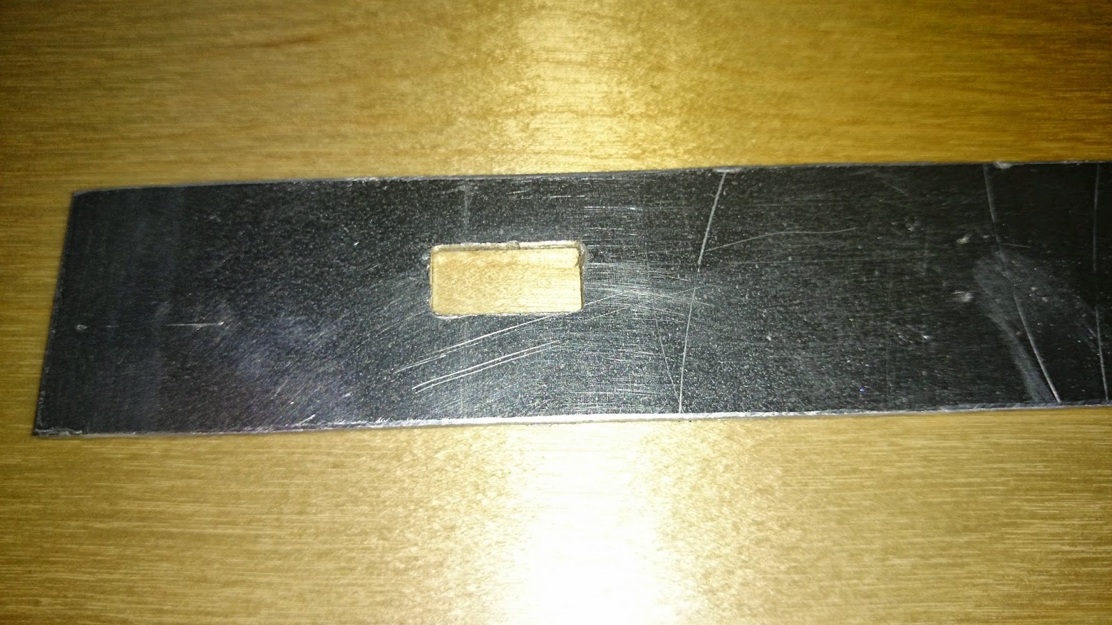
Look the miracle, it was milling the hole without any hassle.
This means I don't need to buy a new spindle motor, because the old one is doing it's job, just the power supply inadequate. Only the rotation speed control's question need to be solved, and find out the maximum feed rate.
Now coming the milling of the front and back panels of the external PSU.
Yesterday morning I connected the new PSU in without any speed control.
Look the miracle, it was milling the hole without any hassle.
This means I don't need to buy a new spindle motor, because the old one is doing it's job, just the power supply inadequate. Only the rotation speed control's question need to be solved, and find out the maximum feed rate.
Now coming the milling of the front and back panels of the external PSU.
Feliratkozás:
Bejegyzések (Atom)