A következő címkéjű bejegyzések mutatása: CNC. Összes bejegyzés megjelenítése

2022. június 6., hétfő

CNC Router Reborn 3.

I'm just able to move forward with this project just only small steps.
As I fitted the 600VA power supply for the spindle into a two unit high drive bay, I realized that it has a fan at the front. I didn't want to cover it with the regular PC plastic front panels to allow the air flowing.
So I designed a proper grill for the front, what match the PC front design.


Printed and assembled to the PSU:


I also worked on the spindle controller. It is ready made controller bought from the Aliexpress. It has controls and display, but needed some mounting hardware to fit into the PC enclosure. It is also 3D printed:


Assembled:


Wired together, the whole set. Measured the PSU. The LED display was a bit flashy from the first moment, finally completely stopped to work. As I not really have too much time to troubleshoot a such cheap, undocumented electronics (not worth the effort), so I ordered a few different kind of controller for a few bucks. This project put aside until those arrive.

2022. április 13., szerda

CNC Router Reborn 2.

Its been a while I write about the CNC project. It is in the state, I eventually work on it, so it advance really slowly.

It is time to write about the current state.

What happened since last time:

  • Mounted the controller hardware (GRBL controller, stepper drivers, except the spindle controller into the PC box)
  • Cut the back panel to fit into the place of the original PC card back panels
  • Rewire the entire frame with longer cables (needed to be able to put the new controller case to the ground next to the CNC routers table)

The controller from inside:


The back panel (hole for the connectors still need to drill):


The new dymo heathshrink labels in action:


After I finished the cabling realized that one of the connectors miss the screw lock ring. Am I so idiot that it fall from the connector before assembly and I didn't realize it?

Nope. I just found on the floor:


What a shitty material those guys use. I fall from a meter to the floor and broke into pieces.

What's next:

  • Drill the connector holes to the back panel and assemble the whole motion control
  • Create mounting hardware for the spindle controller (probably 3D printed)
  • Create a front panel with vent holes for the 600W PSU
  • Put everything together and test is


2021. szeptember 25., szombat

CNC Router Reborn 1.

Back in 2014 I bought a CNC Router on the Aliexpress. I learned how to use it. It had several issues, what I wanted to, and started to fix.

Exchanged the undersized linear power supply to two switching ones, designed (and put substantial amount of work) into a new spindle controller. Made several mistakes (like broke one of the power supplies, later killing it completely during a repair effort). Even designed (and started to build) a dust collector for it.

At the end of the day I realized, that the unit will never fulfill my requirements. So I gave it up. Once collected some controller parts, to make it work just on "as is" bases, but left the thing lying around in my workshop.

The substantial problems I had:

  • Realized, the the 3040 form factor just a bit small for me. I rather go with 6040 or even 6090
  • The 300W (later changed to 400W) spindle motor is too small for me. The used brushed DC motors have very low torque at low speed. For milling aluminum it would need low rpm, high torque. I can't put bigger motor (or even low power BLDC) into the 52mm holder. To put a bigger holder I would need to replace the complete Z-Axis, as the holder made from a single piece of metal with the bearings and ball screw nut integrated.

Finally I decided, it would cost to much, to make it perfect, while the size kept still too small.

I'm here around 5 years after I last touched it.

I constantly pushing my son, to do something other than computer games, in his free time. A few weeks earlier he come up with some idea. We realized that he will need a CNC Router for his project.

I felt, that this is a good opportunity to rebuild my CNC router and also put me back on track.

The plan:

Build a new controller box for the CNC router, put together a new toolchain for it. I want to do this with mainly the parts I already have. The goal is to sell the CNC3040 at the end of the day to be able to build a bigger one.

The control box:

An old PC midi tower. This kind of thing always lying around as I live from computers in the last almost 30 years.

  • A mini-ITX motherboard: Gigabyte GA-E6010N - this one I bought newly
  • 8GB DDR-3 RAM - had it already
  • 60GB SSD - had it already
  • 600W 48V PSU for the spindle motor - from the last CNC repair effort
  • 100W 24V PSU for the stepper drivers - from the last CNC repair effort
  • 350W Chieftec PC PSU for the motherboard and the GRBL controller - had it already
  • Solid State Relay - had it already
  • GRBL controller board - bought for the CNC years ago
  • TB6600 stepper drivers - bought for the CNC years ago
  • Spindle speed controller - bought for the CNC years ago
  • Connectors - scavenged from the old CNC controller box

1. I put together just the PC on my desk to install the control software


Installed an Ubuntu Desktop 20.04 LTS onto it. Switched to LXQt to decrease the resource requirements. Installed Docker on it (from my work I became a Docker junkie in the last years), and added a CNCjs container. It still need some tuning, but it can only be done, when the controller is connected and I see what needed.

First mission accomplished. The CNC.js started to work.


2. Start to put together the control box

Drilled out some pop rivets from the PC box back. Removed the extension card holder/ATX cutout assembly. Cut it into two piece at the first extension card (the first card can be used even on a mini-ITX board). When it was done, put it back with new pop rivets.

Cut a few HDD holder ears in the 3.5" bay. It was needed to be able to assemble the 100W PSU in. Fortunately there was a few holes on the bottom for mounting the PSU without drilling.

Cut two L shaped aluminum extrusion for the 600W PSU to fit it into the 5.25" bay. After some drilling, threading, sanding, it went into it's place.

From the old PC PSU connector male (I have it unassembled) created a cable for the SSR and assembled the SSR in (It fit into the holes of the case top fan).

The idea with the SSR to be able to start the two additional PSUs when the PC soft start button pushed.


I altered the PC PSU a bit.

  • Added a bigger hard switch to be able to handle the two additional PSU
  • Added a screw terminal block switched mains output - I don't want to see more than one mains outlet at the back of the box.
  • Replaced the noisy (faulty) fan

Assembled the things above plus the PC motherboard, SSD drive into the cabinet.


I know, that this thing doesn't look more like a standard PC (nothing interesting in it, we built like this hundreds of times), but more to come.

2017. augusztus 26., szombat

Pen Plotter 4 - InkScape/KiCAD drawing toolchain

The first test of the plotter, this one:


was done with the following software toolchain:
I draw that spiral with InkScape, saved as DXF and converted with the DXF2GCODE software from sf.net:
https://sourceforge.net/projects/dxf2gcode/
Tried to use a few gcode sender, but finally kept using the Rasberry PI/Ubuntu/Octoprint set. As I'm quite familiar with it from my 3D Printing past.
The toolhain above has some drawbacks:

  • I wasn't able to produce correct scaling. I don't know it is just my inability or problem of the software used.
  • The DXF2GCODE is more likely a basic CAM software and not just a plug and play conversion solution. The plotter needs much simpler gcode than a CNC Router, and the functionality of working with tools, pockets unnecessary at this point.
  • There is a drawn line between the home point and the start of the spiral what isn't in the original drawing. It is not caused by the toolchain. I'll will come back to this issue later

At this point I was thinking a bit differently. The DXF is a mechanical CAD format, so not really designed for pen plotters, but the HPGL definitely the language of the HP pen plotters.
I searched for a program what is able to convert HPGL to G code. I found a few converters. None of them was fit into my needs. Most of them was not able to convert the HPGL AA arcs to G2, G3 gcodes. This conversion needs some trigonometrical knowledge so it looked hard to achieve for some programmers. After a few trials I gave up to use something I found on the net.
So I wrote one. It is in the github repository of the plotter:
https://github.com/sufzoli/suf-3D-Plotter/tree/master/SW/Hpgl2Gcode
It still has some problems like incomplete error handling and lack of path optimization, but does it's job.
Now let see, how the toolchain works
Here is the original drawing:


First all of the object in the drawing must be converted to path, otherwise it will not represented in the HPGL output:


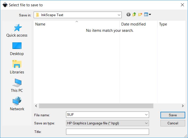
When it's done, you can save it as HPGL:


Now the bit tricky part coming:
The InkScape HPGL save dialog default parameters are mainly setup for cutting and not drawing plotters. Therefore most of them need to be changed according to the following:


Now you have to convert it to G code.
I used two different settings. The reason is the G code of my plotter use M280 P0 S50 command to lift the pen and M280 P0 S0 to put it down.
The usual CNC routers use G1 command to move the Z axis. The widely used G code simulator CAMotics Doesn't understand my pen up and down commands, so for the simulation I changed them to G1 Z5 F50 and G1 Z-2 F50 respectively:


And here is the result in the simulator:


As it looked good, I made the conversion for the plotter:


As you can see, the PenUp and PenDown parameters are missing here. The reason of this that it was setup in the application config file.
After this uploaded it to the Octoprint and sent out to the plotter. The result is disaster. It drawn a 2cm dashed line from the home point towards the starting point of the drawing, then drawn the whole drawing in the air (pen lifted).
I known what is the problem, from the first moment. It is the same problem what I mentioned at the beggining of this post (line from the home point to the beggining of the spiral). The G code commands are not executed in order.
I know about the Marlin firmware that it queue the commands and some commands are executed in order and some out of order. I was reading the source code of the Marlin for a few hours to find, how to change this behaviour Unsuccessfully. I gave up at this point and asked in the Marlin forum.
The answer was much more easier than I ment. Adding an M400 command (wait for finish of the previous commands) before an out of order command solve the issue. I wasn't even need code change for this as my pen hadling commands are represented in the configuration file.
The only trick here that the handling of the multiline string in the .Net config file. So the parameters look like this now:
M400
M280 P0 S0

And finally the result:


The converter I wrote also understand the HPGL output of KiCAD. It can be used for drawing and not PCB milling. This will come later.

2017. július 31., hétfő

Pen Plotter 3. - Working

It is finally working.
Built the whole thing, assembled, then redesigned most of the pen holder.
The problem was the following:
  • The SG90 microservo I intended to use was not strong enough
  • The line I wanted to use to pull up the Z carriage was a bad design decision
  • The arduino was not able to provide enough current to the stalled microservo, so it rebooted when the pen pulled up.

In the new design:

  • The SG90 replaced with a more powerful MG995
  • The servo moving the carriage directly
  • Added a 6V regulator for the servo, what gets its power from the beefy 12V PSU and not the arduino.


The electronics on the head still messy as I don't designed a proper PCB yet (but it will only happen when I finish the milling and the laser engraving head design):


And finally here is the first video of the working unit:


2017. július 5., szerda

Pen Plotter 1.

I'm not documented this project deeply, step-by-step. Now I'm just writing where am I today with the build. Mainly pictures.
More than three month ago I had a conversation with my son. He told me that he want to build a "drawing machine" essentially a pen plotter together with me. I started to design one. After a few conversation he told me that he wanted to build it from Lego.
I was already too deep in the designing already, so I didn't want to stop. In addition I was planning to add exchangeable head to be able to use it as a light router and a laser cutter/engraver.
I think the design mainly finished:


I left out a few things from the design, like drag chain, screws, spacers, timing belts.
During the design process I already printed some of the parts:


As you can see, there are some assembled parts also on the picture, like the Y axis drive (round white thing in the center) and Z axis carriage (the green thing).
How the Y axis timing belt mount into the holder:


Lots of holes, the base plate:


X axis assembled:


continue...

2017. május 26., péntek

Cyclone PCB Factory 5.

Oh, noooo.
I just tried to attach my Dremel to the Cyclone:


This doesn't work.
Just found out that I've a Dremel 300 and the Z axis is designed for the Dremel 3000.
There are no ready design available for the Dremel 300. Shit.
I've a few options:
Design a Z axis for my Proxxon.
Buy something from eBay/Aliexpress (775 DC motor, CNC spindle), they have ready Z axis design.
Buy a Dremel 3000.
After a half day thinking, evaluating the options, decided to buy a Dremel 3000. It needs the least effort now. I was able to find one for ~$40.
I ordered it in the morning. It landed in the FoxPost's box on the same evening (It was fast):


2017. május 23., kedd

Cyclone PCB Factory 3.

I finished (almost) the mechanical build:


I'm quite happy with it. This is the first time when my son helped me with my projects. :-)

There are two things I want to check/correct in this build:

  • I wasn't able to buy M3 grub screw. So I assembled with normal screws and adjusted the gear placement for it. I'm not happy with the solution, so I'll try to get grub screws somehow.
  • The Z axis threaded rod maybe to long. I 'll check when I put the Dremel in, and adjust the size.

2017. május 22., hétfő

Cyclone PCB Factory 2.

I started to assemble the Cyclone.
How does it look like now:


When I tried to assemble the moving bed (Y axixs),  I realized, that it has a problematic design. It is only designed for a single size PCB. If I want to mill varying sizes, I've to change it to something else.
So I designed a different one:


It is able to lock various PCB sizes.
I started to print the parts of it.
It looks like the Geeetech printer struggling with some challenges:


I clearly know, what is the problem. This model has no object cooling. I'll design some for it, but not now. Actually, I know, how can I deal with this. So I was able to print this part finally.
The assembly comes later.

2017. május 21., vasárnap

Cyclone PCB Factory 1.

I've seen in someones post on the Facebook this:


I decided, that I want one.
As one of my 3D printers (the Geeetech) started to work. This time reliably. I printed out all of the required plastic parts. From that pink PLA. :-)


Yes, this picture was already published, but I habitually late with my posts.

2015. augusztus 13., csütörtök

CNC Motor Driver 13. - Front Panel Board

More than a week ago the boards finally arrived:


Then I soldered the parts into it:


I picked one of my Nuvoton development board, cut it to it's parts, and soldered the missing headers, to be able to use it as an ICE programmer/debugger:


Finally, I started to rewrite the controller's program, to the new pin configuration. During this process, I also want to little bit clean up the code.
To test the board is working, I wrote a "Hello World" for it. :-)


The board looks like working so far. The next step would be to finish the conversion/clean up the code.

2015. június 23., kedd

CNC motor driver 11. - Learning Chinese, front panel schematics

Reverse Engineering the CNC control board

During the weekend I was trying (still unsuccessfully, but I don't give up) to get the PWM signal generated by the LinuxCNC out from the parallel interface/stepper driver board.
I would like to achieve without soldering (just to have some challenge).
First of all, about the board.
The machine arrived with a JP-3163B board in it, plus and additional stepper driver for A-axis. Actually, I'd like to keep this board and I want to get as many things I can out of it. The board in question is a version 3.9.
What I found out, that the documentation widely available (and already mentioned by me earlier here), is not completely correspond to my board. Even, if I check the pictures of the boards in sale currently on the AliExpress and eBay, are the same as mine, but the documentation is the other (in fact for the v3.6).
If we are talking about the stepper drivers, and the inputs that are the same, but the additional secondary relay, the spindle drive, the jumpers, or the LED's for the A-axis are totally different.
The only information I can get is the Chinese text from the board itself (not to much).

Part of the 3.6:


And the 3.9:


As you can see the upper has 3 jumpers and the lower has 5. (If you didn't realized, the fifth located next to the parallel connector.)
Actually I'm trying to collect as much information about the boards as I can. I found this text somewhere:

现出售的是最新的JP-3163B V3.9版本,增加了延时启动功能和风冷功
能,延时启动是为了更好的保护驱动器不易损坏(风冷为开时,只受Z轴
方向吸合继电器2输出给电磁阀风冷,风冷为关时,做继电器2使用),另
外:本店的手柄只支持以前的V3.7 V3.8 V3.9版本,V3.6版本是不能用
手柄的,请购买手柄的客户买雕刻机手柄时,与店家联系,了解您购买
的板子是否可以配用JP-392Q控制手柄.

Translated (google translate our friends):

Is the sale of the latest JP-3163B V3.9 version, adds delay start function and air-cooled power
Energy, delay start is to better protect the drive easy to damage (air to open, subject only to the Z-axis
Direction of pull solenoid valve relay 2 output to air cooling, air cooling is off, do use relay 2) and the other
Outside: We handle only support the previous version V3.7 V3.8 V3.9, V3.6 version is not used
The handle, the handle when your customers buy buy engraving machine handle, contact with the store, understanding your purchase
Whether the board can be used with JP-392Q control handle.

This is far from perfect, but at least we can see that some changes in the cooling and the delayed start is added somehow to the spindle drive.
About the LEDs, specially the upper three. On the original board I seen somewhere else English text stating the following:

LED1 (Red) - PWR - Power
LED2 (Green) - A-OR - A-axis direction
LED3 (Green) - A-PU - A-axis step

On my board:

LED1 (Red) - 电源  - Power supply
LED2 (Green) - 主轴 - Spindle   (Pin 1 of the parallel port)
LED3 (Green) - 使能 - Enable    (Pin 14 of the parallel port)

I also tried to get some information about the jumpers

JP1 - 内 5V / 外隔离 - Within 5V / outer barrier (Internal 5V / External supply ???)
JP2 - 使能开 / 关 - So able to open / close
JP3 - 风冷开 / 关 - Air cooling on / off
JP4 - 模拟量开 / 关 - Analog On / Off (When I switch this of the previous constant 10V disapear from the spindle control)


JP5 - 手控开 / 关 - Manual on / off

Some of the pins of the parallel port are working differently (or has connection to the Spindle control) than it written on the documentation I found:

1 - Spindle On/Off
14 - ??? (Switch On/Off the LED3, but I didn't found any other impact yet)
16 - Relay 2 (It clearly switch on and of the Relay 2, instead of the stated NC)
17 - ??? (Actually I didn't found any impact, it may NC)

This is the current status. I didn't have more time to work on it. I'll definitely continue this, until I'll able to get out the PWM signal in some way.  

Front Panel Schematics

I finished the first version of the front panel schematic design. It is in the github repo:


I'd like to add some comments to it:
  1. I added lot of external connectors what will not be used but give place for future development
  2. The controls are still fuzzy. I may change some hard buttons to a menu based something controllable via the rotary encoder and it's button. This need some tweaks in the hardware also. This means, the schematic will get some slight modifications before the PCB design.
  3. The software spindle control has no additional circuit, it is just two pins now on a connector. It will be an add-on board with maybe some protection diodes, level shifting circuit, or optocouplers. It will be based on my finding in the first part of this post. On the other hand, I do this, because this keep the things open to connect different kind of CNC boards.
  4. The MCU pins are significantly different from the ones are on the current software implementation (the software will be aligned later). The cause of this, is a misinterpretation of the MCU pins by me. I mixed up the ADxx pins with the AINx pins. The first is external digital parallel bus, what I don't use, and the later is the inputs of the AD converter.


2015. május 31., vasárnap

CNC motor driver 10. - Logic Psu build

Yesterday I soldered the parts into the board, I realized three mistakes, what I made.
  • The designed connectors are bigger, than what I wanted. So I 'll have 3,96 mm spacing connectors, instead of the 2,54 mm ones.
  • Drilled a 1,5 mm holes for the connectors instead of the required 2 mm ones. Fixed easily.
  • There is an additional LC filter at the output of the circuit. I designed a 100uF/6,3V B size tantalum capacitor into it, but I bought 100uF/10V D size ones. I was thinking. If I not solder this now, will this prevent me from trying the circuit out? Not. So I just keep it this way, and buy new caps on Monday.


As I finished the build, I wanted to test it. I was specially interested in the noise generated by the circuit.
As I had no cap in the output LC filter I soldered an old 100uF cap directly to the testing 470ohm load resistor, and tried to figure out the noise generated.


It was so low that I can't find it in the enviromental noise picked up by my oscilloscope.


And finally the output voltage is good enough.


2015. május 29., péntek

CNC Motor driver 9. - Miscellaneous things

In the last weeks the project not advanced so much, but various things happened around it, what I want to write about.

Logic PSU
In the mean time I designed the test circuit/board for the power supply of the low voltage parts of the circuit. The MCU, the measuring amplifiers, the display will run from 3.3V (I planed to use 5V supply originally, but the display I'm using is not able to run from it). This supply finally not as cheap I wanted to have. It was clear that I need a switching mode supply, and a chip with high voltage capability. I know that a few hundred milliamps is not to much, and the whole circuit is powered from the mains and not batteries. This is a good candidate for some three leg standard regulator or LDO, but...
Always, that but.
the whole circuit will run from a single 48V supply. Generating just 100mA with a standard regulator means you have to dissipate 4.47W on the regulator. In addition the standard three leg regulators are not designed for 48V input voltage.
So the decision is to use HV buck regulator. Especially the LM2594HV-3.3 model from TI.
I designed a circuit around it:


And a PCB for testing:


The finished board (population come later):


MCU Arrived
When I started this project I selected Nuvoton's M054LDN for it. It has 16+4K FLASH what looked enough to me. I have an M0516LDN based development board in my hands, so I started to write the code on it. As the project advanced it become clear, that the code will not fit into the 16K. There is two factor behind it: the character table used for the graphic display, and the floating point library used by the PID controller.
But there is a problem. At the local reseller I just found the M054LDN and the M0516LAN and not the M0516LDN. This A instead of D means something here. It is the revision of the device. Together with other changes the rev D. has FIFO capability on the SPI interface what I'm extensively using for the display driver, and really don't want to throw it away.
So I looked around, and found what I needed on the AliExpress.
It arrived also this week:

BEMF
There is some comments on the Hackaday.io page of the project from Andrew and Hacker404 about suggesting to use Back Electromotive Force to measure the rotational speed of the motor without sensors as a more standard approach, than the one I used. Here is two article explaining this technique:
http://acroname.com/articles/back-emf-motion-feedback
http://www.precisionmicrodrives.com/application-notes-technical-guides/application-bulletins/ab-021-measuring-rpm-from-back-emf
As I decided to keep developing the controller based on my idea, really think this as something worth to try.
Here I collected the advantages and disadvantages of BEMF against my techniqe:
+ Way much simpler circuitry required for the control and measurement
+ Lower frequency can be used for the PWM control what decrease the switching loss and increase the possible precision (at 10kHz with the same MCU I can achieve 2500 steps instead of the current 250)
- Less precise measurement. There is several factor reducing precision (noise, measurement timing, calibration requirement)
- Calibration requirement at the enduser. With my method you just need to find out the number commutator segments, and you ready. With BEMF, you have to go through the entire rotational speed range and match the measured voltage with a measured rotational speed (optical encoder, hall sensor, etc.)
- Noisier operation. The motor running from low frequency square wave produce more noise than running from clean DC.
- Not possible to use 100% duty cycle. Need time for measurement.
Anyway. I think it worth to try this method, after finished the current one.