2021. október 15., péntek

Gigabyte and modular power supplies

On the side of the CNC router project (as always) I started an other one. This is clearly just a PC project. Build a NAS from the things I have on hand (ceiling cleanup 😂).

During the long years, I used several - called modular - ATX power supplies. Those things allow you to clean up the cable jungle a bit, what always shown up inside the PC cases, by allowing you to detach unnecessary cables from the PSU. These are the peripheral cables used for the mass storage, graphics cards, etc.

The connectors on the supplies for the modular PSUs are not standardized, usually use the same kind of connector (2 row, 6 or 8 pin, Molex Mini-Fit).

Yes, I bought PSUs from different vendors (Gigabyte, Chieftec, etc.). Yes, I never labeled the cables. And yes, I keep those in one box. This means, I don't have a clue, which cable belong to which PSU.

For the NAS PSU I needed several cables (in hot swap bays, I plan to use 14 disks). If I mix those up, I can imagine the firework it can cause.

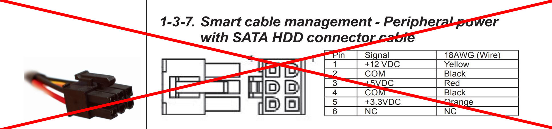
The subject currently is a 550W Gigabyte Odin (I also have an 800W somewhere just not found in the ceiling yet). I downloaded the manual of it. It has the connector pinout in question. (Indicated, not to use it as is bad)

I started to starch my head. None of the cables in the box has this pinout.

DMM on. Measure.

My suspicion become true. The manual is garbage.

This is the correct pinout (the connector drawing is from Molex and show the connector on the PSU itself), and it correspond to all of the cables in my box (it is maybe a coincidence, but Gigabyte, and Chieftec use the same pinout):


2021. szeptember 25., szombat

CNC Router Reborn 1.

Back in 2014 I bought a CNC Router on the Aliexpress. I learned how to use it. It had several issues, what I wanted to, and started to fix.

Exchanged the undersized linear power supply to two switching ones, designed (and put substantial amount of work) into a new spindle controller. Made several mistakes (like broke one of the power supplies, later killing it completely during a repair effort). Even designed (and started to build) a dust collector for it.

At the end of the day I realized, that the unit will never fulfill my requirements. So I gave it up. Once collected some controller parts, to make it work just on "as is" bases, but left the thing lying around in my workshop.

The substantial problems I had:

  • Realized, the the 3040 form factor just a bit small for me. I rather go with 6040 or even 6090
  • The 300W (later changed to 400W) spindle motor is too small for me. The used brushed DC motors have very low torque at low speed. For milling aluminum it would need low rpm, high torque. I can't put bigger motor (or even low power BLDC) into the 52mm holder. To put a bigger holder I would need to replace the complete Z-Axis, as the holder made from a single piece of metal with the bearings and ball screw nut integrated.

Finally I decided, it would cost to much, to make it perfect, while the size kept still too small.

I'm here around 5 years after I last touched it.

I constantly pushing my son, to do something other than computer games, in his free time. A few weeks earlier he come up with some idea. We realized that he will need a CNC Router for his project.

I felt, that this is a good opportunity to rebuild my CNC router and also put me back on track.

The plan:

Build a new controller box for the CNC router, put together a new toolchain for it. I want to do this with mainly the parts I already have. The goal is to sell the CNC3040 at the end of the day to be able to build a bigger one.

The control box:

An old PC midi tower. This kind of thing always lying around as I live from computers in the last almost 30 years.

  • A mini-ITX motherboard: Gigabyte GA-E6010N - this one I bought newly
  • 8GB DDR-3 RAM - had it already
  • 60GB SSD - had it already
  • 600W 48V PSU for the spindle motor - from the last CNC repair effort
  • 100W 24V PSU for the stepper drivers - from the last CNC repair effort
  • 350W Chieftec PC PSU for the motherboard and the GRBL controller - had it already
  • Solid State Relay - had it already
  • GRBL controller board - bought for the CNC years ago
  • TB6600 stepper drivers - bought for the CNC years ago
  • Spindle speed controller - bought for the CNC years ago
  • Connectors - scavenged from the old CNC controller box

1. I put together just the PC on my desk to install the control software


Installed an Ubuntu Desktop 20.04 LTS onto it. Switched to LXQt to decrease the resource requirements. Installed Docker on it (from my work I became a Docker junkie in the last years), and added a CNCjs container. It still need some tuning, but it can only be done, when the controller is connected and I see what needed.

First mission accomplished. The CNC.js started to work.


2. Start to put together the control box

Drilled out some pop rivets from the PC box back. Removed the extension card holder/ATX cutout assembly. Cut it into two piece at the first extension card (the first card can be used even on a mini-ITX board). When it was done, put it back with new pop rivets.

Cut a few HDD holder ears in the 3.5" bay. It was needed to be able to assemble the 100W PSU in. Fortunately there was a few holes on the bottom for mounting the PSU without drilling.

Cut two L shaped aluminum extrusion for the 600W PSU to fit it into the 5.25" bay. After some drilling, threading, sanding, it went into it's place.

From the old PC PSU connector male (I have it unassembled) created a cable for the SSR and assembled the SSR in (It fit into the holes of the case top fan).

The idea with the SSR to be able to start the two additional PSUs when the PC soft start button pushed.


I altered the PC PSU a bit.

  • Added a bigger hard switch to be able to handle the two additional PSU
  • Added a screw terminal block switched mains output - I don't want to see more than one mains outlet at the back of the box.
  • Replaced the noisy (faulty) fan

Assembled the things above plus the PC motherboard, SSD drive into the cabinet.


I know, that this thing doesn't look more like a standard PC (nothing interesting in it, we built like this hundreds of times), but more to come.
2021. szeptember 17., péntek

Restarting

As you may noticed, I didn't write anything since March. I wasn't too active before in the last two years either.

Many things happening right now around me, what is connected to the blogging, my hobbies even my work.

I'm planning to write more frequently from now on. Restart few previously abandoned projects. We will see, if this plan come true.

2021. szeptember 11., szombat

9/11

Let me tell a story. My story.

1996 December

I was visiting New York with my mother. It was on an invitation from a friend of my grandmother. We were there for more than 3 weeks. I don't want to write here about the full trip, just highlight two details.

We were visiting the Empire States Building (the top of it). Waiting for more than 5 hours in the line to get to the elevators. Even become dark when we where able to reach the roof and see the city from there.

On the last day of the trip, just a few hours before we left, I seen a sign somewhere that at the Pier 86 you can see the USS Intrepid museum. Unfortunately we had not enough time for the visit. It was in my mind: Next time.

2000

I was involved in the printing industry. We were planning a trip to Düsseldorf to Drupa exhibition. My father got seriously ill, so we canceled the trip. Next year held a similar exhibition in Chicago the PRINT 01. 

2001 September 6.

My father got better, so we headed to Chicago. The trip was organized by the Hungarian printing association. Altogether 10 people went there. We decided to visit New York at the end of the trip for two days.

2001 September 9.

Arrived to New York. Took a bus ride to have some view as for some of the people this was the first visit. We were even at the WTC to look around.

2001 September 10.

Two of our colleagues wanted to go to the WTC, next day, in the early morning, to see the city from the top. They also invited me. I decided, rather not go there. First I was on a skyscraper trip 5 years before, second, I wanted to visit the USS Intrepid, what I missed in 1996.

The two colleagues didn't speak English, so they decided to come with me to the museum.

How coincident can save your life

2021. március 12., péntek

EPROM burning 21/25V 2.

 As it wasn't a big deal project, I made the drawings fast, and ordered the boards. Also as I didn't want to use some fancy SMPS for the boost voltage conversion, so I picked the good old MC34063 used a switchable feedback divider and that's it.


The board is arriving from the JLCPCB, with the cheapest manufacturing and shipment method. I left this project laying around for a long while now. I'm not willing to pay any extra for my laziness.


2021. március 9., kedd

EPROM burning 21/25V 1.

 After my last Fake in China post, I continued to work on the 2716 EPROM burning. I ordered a second batch of 2716's from a different source. The new series looks more promising:


Same chip size, two different date code. I think this is still a chinese copy, but may works.
Also, I've a different issue here, what I just barely realized last time.
The TL866II programmer what I use, doesn't support the 21V Vpp printed on the top of the case. Even, according to the original ST documentation, it should be 25V. The programmer only support 18V. It is not enough, even the chips would be genuine.
This is great, just I don't like it.
This is a hack solution to me. I want to have a proper adapter, I'd like to see the pin detect function still works, I want to use a regular wall wart adapter instead of a lab supply, I want to have the 21V/25V programming voltage switchable, I want to protect my TL866II from faulty chips.
I asked a question on a forum, how the pin detect function of the programmer works. On the side I had a cloudy idea in my head:
What if: I just connect the original programmer pint to the chip through a diode, while clamp the programmer side to the ground with a high value resistor. In addition use one n-channel mosfet, with a zener to detect if the voltage from the programer is more than - let say - 12V. With this n-channel mosfet pull to the ground a p-channel mosfet's gate connected to the external programming voltage and the chip's Vpp.
On the side of why even you need those chips, why you not build another programmer from scratch like answers I got to relevant:
The schematics of the TL866II:
And a kind of solution from a german site:
This later link contains a schematic, what is exactly the same what I have in my mind except it was realized with bipolar transistors instead of mosfets
Károly Molnár, István Sümegi - Thank you for the links.
So the project starts here. The real programming in this case can wait.
In addition to the mentioned circuit I plan to add a boost converter with switchable output (21V/25V from a 12V input), plus a zener and a resistor for every pin to protect the programmer.
This is how my abandoned projects are come into existence. :-D
The design will be available here when it is ready for this:

2021. január 31., vasárnap

Hi-Fi Rack - Motorized turntable tray 3.

This year I decided, to complete some previously abandoned projects of mine. I'd like to finish one of those in every month. It is just a plan and not a promise (I don't want to fell into the trap of unkept new year's resolutions).

The first one in the row (for January) is my motorized turntable tray. The previous posts about it can be seen here:

Since I restarted January, many things happened with it:

  • Added the final electronics
  • Changed the TI DRV8825 stepper driver to Trinamic TMC2209
  • Almost completely rewritten the code, based on TMCDriver and AccelStepper, while keeping the original touch sensor library.
  • There was an achievement from my side, that after a long struggling period, my 3D printer is back online and working stable, so I was able to add 3D printed parts. This way a new cable management arm come into picture instead of the unreliable tape used previously. It is used for the touch sensor cable and the mains cable. For the audio cable I may create a second arm sometime.
  • I also 3D printed the holder for the connector at the back panel.
  • Created a kind of power breakout box (temporary solution until the proper supply is made):
    It has:
    • +12V - Wall Wart adapter for a time being
    • +5V  - Wall Wart adapter for a time being
    • Earthing (for the touch sensor)
    • Serial connection
  • Mounted it into it's final place

While I was writing the serial communication part of the code (it will be used later), a weird issue raised.

The connection to the PC just created unusable data stream. A complete mess. Even I changed the USB-Serial adapter. I didn't understood why. Then an idea pop into my mind, and...


Yes, I used a 12MHz crystal instead of 16MHz. This means, everything working correctly, except the serial communication. When I used 115200 on the arduino side and 86400 on the terminal side, the communication eventually started to work normally.
I didn't wanted to keep it this way, so changed:


The complete electronics, in it's place with the motor and the cable management arm


The power breakout box


Now only a few things left to do:

  • A better GT2 pulley mount
  • A second cable management arm for the audio cable
  • The next phase of the project, what will contain the proper power supply also
Working on my desk:


Project finished, mounted into it's final place:


The design and the code reside here: