2018. december 22., szombat

Status

It's been long time since I didn't write anything on this blog.
Actually I just didn't have lust to write. It doesn't mean, nothing happened.
The main reason I writing now is the status of my Curve Tracer project. After a long struggling period I achieved the first milestone of the project. It started to work. I mean the whole measure chain is working, but there is a long road ahead still, until the finished product.
As I'm talking more and more a few "audio related" people, I went back a bit into my childhood, and started to work on my audio equipment.
Repaired and modified my good old NAD5120 turntable. Repaired my Mission 705 speakers, collected a few retro audio components from the eBay.
Now I have a fairly good sounding system. I'm planning to add some DIY components in the future (going back in electronics, where I started)
There is something itching inside me, since I first saw a Fostex full range horn speaker in a DIY book. It was at least 5 years ago. Since then I'm thinking about to build a pair. As my audio equipment started to work, I felt, it is just the right time to make my hands dirty.
I started to build a Fostex FE108E Sigma based box. To be precise, the recommended enclosure from Fostex's web site.


2018. szeptember 13., csütörtök

Fake in China (DIY Curve Tracer 4.)

I'm continuously working on my Curve Tracer in my spare time. I designed a Vishay VO14642 photovoltaic SSR into the circuit. It is quite a nice, but pricey device.
I thought why not try to order it from Aliexpress. For control I also ordered a few from Mouser.
Both devices on the same board:

The original on the left

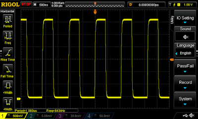
The fake measured

The original measured

This device should have 0,25 Ohm maximum on resistance.

2018. augusztus 10., péntek

Farewell to "freedom"

I've plenty of Freescale FRDM (Freedom) boards at home. For years I was trying to create something from them. Unfortunately it was always a failure. I was analyzing the causes but can't find the reason. I can tell only just one thing we are not compatible with each other.
I'm not an idiot. I was working with MSP430, TI Tiva, AVR, ESP8266, Nuvoton ARM MCUs, STM32 (recently) in the recent years. Usually after a few days of learning, struggling I always found the way, but not with those (Kinetis series).
But they did everything to be successful. Erich Styger is writing an excelent blog (mcuoneclipse.com) on it. I learned many things from him. The Freescale was the only company from all of the MCU manufacturers who was organizing local workshops here in Hungary.
Nothing helped. So I give away my assets connected to the Kinetis/Freedom word to the newly founded makerspace: 1337


Stack of the boards waiting on my shelf to the transport.

2018. július 31., kedd

DIY Curve Tracer 3. - MCU selection

As I mentioned earlier I wanted to change the two AVR MCUs from the original design to a single 32bit one.
Here are my selection criteria:
  • Two at least 12bit DAC channel - One channel is used for the sine wave generation, the second maybe used for the pulse generation (not designed, decided yet, but better if it is available)
  • Two at least 12bit ADC channel - For measuring current and voltage on the DUT. If parallel sampling and/or differential input available is good but not requirement
  • DMA for DAC operation
  • 32 bit core - ARM Cortex-Mx prefered
  • Arduino framework support, free, native C/C++ IDE support (I haven't decided between the two, so the support is necessary)
  • Low cost development board
  • Easily solderable (for me. Means: TQFP accepted, QFN, BGA not - I know this is my personal limitation, but I don't want to learn it right now)
Based on the specs above my choice is an STM32F303RET6:
https://www.st.com/content/st_com/en/products/microcontrollers/stm32-32-bit-arm-cortex-mcus/stm32-mainstream-mcus/stm32f3-series/stm32f303/stm32f303re.html

And the development board for it:
https://www.st.com/content/st_com/en/products/evaluation-tools/product-evaluation-tools/mcu-eval-tools/stm32-mcu-eval-tools/stm32-mcu-nucleo/nucleo-f303re.html

I ordered the board from Farnell yesterday. Today arrived:


Next: seting up the development environment

2018. július 29., vasárnap

DIY Curve Tracer 2. - Concept

Now, I'd like to summarize a few design concept for the project.
I started to work from the 3rd version. As I see now, It can be called as the 4th version because it will have so much differences.

  1. Modular design. I want to be able to use the design either with internal display or with an oscilloscope
  2. Use one 32 bit MCU instead of the current two 8 bit AVR (most probably an STM32)
  3. Internal power supply
  4. Based on the Huntron Tracker 3200S specification - except the 128bit scanning interface
  5. Complettely elliminate mechanical relays (even the reed ones)
  6. Get rid of the most of the digital potentiometers - not really fits for the needs, using resistors and analog MOSFET switches instead
  7. Get rid of the discrete R-2R DAC using an MCU integrated instead
  8. Utilize MCU integrated ADC/DAC/DMA as much as I can
  9. Get rid of the trimpots as I can (probably need to keep it for some offset setting functions)
  10. Keeping the error of the equipment around 1% every place (it is not a high precision equipment. If we want to decrease the error significantly, it cause significant rise in the costs)
  11. Adding the pulse generator as an optional module. It was missing from the 3rd version
  12. Adding the lower current limiting resistor ranges (down to 10 ohms)

First of all, I made a block diagram of the equipment:


2018. július 28., szombat

DIY Curve Tracer 1.

The things are never go the way I planed. A few month ago I put a poll on my blog about the next project. The winner is clearly the Home Automation Center. This thing I barely touched since, and now I'm completely in a Curve Tracer project.
I was visiting Peti Rácz's store/lab to ask him repairing my newly aquired tape recorder. We were talking about various things. He mentioned that he has an ancient Huntron Tracker what is very useful in repairing things. He would buy a newer model, but you can't get anything bellow $2000 (my opinion is this price is a simple robbery). I've checked the current model cost more than $6000 (are you out of your mind???).


I was strated to looking around if a cheap eBay/Aliexpress kit or a DIY project exists. Evaluating various options, finally found this project:
The owner of the project is also a Hungarian guy - Máté Tóth. Asked him to join to the project.
Now, I'm in. Let the journey begin.

2018. július 26., csütörtök

KiCAD 5.0.0

Just realized, that the KiCAD 5.0.0 arrived (four days ago).
The announcement can be read here:
http://kicad-pcb.org/blog/2018/07/KiCad-5--a-new-generation/

It has some promising new features:
- New 3D modelling (the old was almost useless)
- Spice simulation
- Change in the Github based library management
Just to list my pain points.

2018. május 31., csütörtök

Titan Struggling

I'm just quietly asking. It is allowed to look like this after a few month light usage, or after a stacked print? E3D Titan Extruder - original UK version ordered from E3D-Online.


2018. május 12., szombat

Leather instrumentation microscope

This project came from my wife.
A special microscope exists on the market, what has heated bed. It can be used to examine samples from old artifacts before restoration. It specifically used for leather objects in our case, but it can be used for other things also.
The goal is to determine the exact temperature when certain change happen in the material.
This is a time consuming task, the currently used equipment is fairly old, and limited in functionality.
I decided to design and build a new one.
"If the only tool you have is a hammer, you tend to see every problem as a nail."
So, build a 3D Printer!!!
The plan is the following:
Hardware (mostly):
  • Build a heated platform, controlled from an Arduino Mega, Marlin firmware and use PID control for the bed, using an external MOSFET. Measured with the usual 100K NTC (actually disassembled one from the "anettka" original MK8 head).
  • Variable intensity lighting from the bottom (Case lighting from the Marlin)
  • Z axis leadscrew with a Nema 17 stepper DRV8825, and endstop(s). A microscope camera mounted on it. The axis controls the focus of the camera
  • The camera and the Arduino is hooked onto a PC via usb
Software:
I plan to write the following in C#:
  • Control the heating through gcode to achieve the required heating curve (PID tuning also involved)
  • Record the camera image with timestamp and temperature
  • Overlay the parameters (time, temperature) into the recording
  • Manually control the Z axis from the PC
Later:
Autofocus based on the camera picture, convolution matrix and similar computer vision voodoo

For the video and camera handling I plan to use aforge.net framework, what I already used before.

2018. május 6., vasárnap

Home Automation - building docker

I started to build the Docker infrastructure on my Hyper-V servers for my home automation (and other) workloads.
My comfort zone if we are talking about linux is mainly Ubuntu and Debian. I heard from various places that I should use Alpine for Docker. Actually I run already into some prebuilt Docker images what based on Alpine during my daily work. So I decided to build this new system on Alpine thinking it is a good opportunity to learn it.
First:
Downloaded the image optimized for virtualization as guest, configured a Gen2 Hyper-V guest and started it.
Yes, it is optimized for virtualization, but not for Hyper-V. Not even started
Second:
Downloaded the standard image. This was able to start in the Hyper-V so, I installed into the vhdx.
As I'm usually copying the image to create a new virtual machine, the Alpine gets here a plus point from me, as it doesn't need boot process tweaking like the Ubuntu for the disk image copying.
Installed nano, as I'll need to edit some config files in the actual machines, and started to replicate the disk images, create additional virtual machines
Third:
I've set the IP address, machine name, DNS, gateway, etc. Just the usuals things.
After reboot it won't start anymore. The reason is the chronyd. As it wasn't able to aquire the time from the internet, waited indefinitely in the boot process. No console, no SSH.
Ok. machine killed, recreated from my base image. Looked around, find nothing. Finally checked the contents of the alpine chronyd package and find out, that I can add the timeout option into the /etc/conf.d/chronyd file. In the ARGS add -t 60
Fourth:
Configured SSH for my needs, added the additional repo for some extra packages needed by the Docker engine.
Installed Docker on all of the x64 machines, setup startup of the Docker
Fifth:
Starting Docker on the machines give this error:


After several attempts I failed to resolve this issue, but find some articles discussing why the Alpine doesn't fit to the task:
http://janhapke.com/blog/alpine-linux-sucks-for-hosting-docker-containers/
http://www.nathanbak.com/?p=37

So I decided. Forget this and go back to Ubuntu. My next try will be on the shiny new Ubuntu 18.04 LTS

Home Automation center

In 2016 I started to work on a home automation project what I finally abandoned.
Since then, I feel more and more, that I need something for the task. As I finished the repairing of my Robo3D printer, I had no current running project, so I started a poll on my (Hungarian) blog asking for my next project.
The home automation center was the clear winner of the poll. I started to think, what to do, and how.
The things I decided:

  • I want to build the system incrementally beginning with the center
  • I'll use OpenHAB as the center (this supports my FHT/FS20 Conrad thermostats)
  • I want to build it as a High Availability solution
  • I want to be able to use it even the internet connection is broken
  • I want to run it on some kind of SBC
  • I want to use 64bit system - to be as future proof as it can
  • I want to use things I already have


About my current IT infrastructure - It has big impact to my decision:
I've two VPN connected sites, one is my home and the other is my office. I've currently 4 MS Hyper-V servers. 3 in the office, one at home. The system will be based mainly on Docker.
I plan to build a 1U rack box, containing two Pine64 boards, two 5V PSU and maybe two disks.
I'll build two Docker Swarm clusters:

  1. An x64 Cluster: Two Manager/Worker combined nodes placed on two Hyper-V guests in the office and an additional Manager node on my home Hyper-V.
  2. An ARM Cluster: Two Manager nodes placed on two Hyper-V guests in the office and an additional on my home Hyper-V, the two Pine64 will act as worker nodes.

I want to place the OpenHAB containers on the Pine64s, plus GlusterFS, plus HAProxy as HA solution.
To the x64 Cluster goes the supporting components:

  • Private docker registry
  • Zabbix or Nagios monitoring
  • Additional containers needed for my work (not Home Automation related)

The location/implementation of data collection, MQTT based control is not decided yet.
When the system above is up and running, I'll go further with the integration of sensors and actuators.

And yes, before you ask: - I'm a complette idiot. :-D

2018. május 1., kedd

Robo3D reconstruction

Its been a while I didn't write anything.
In the last month I had not too much time to work on my projects. I just focused on one thing.
It was almost five years ago that I started my long struggling journey in the 3D printing. At that time my intention was to use the printed parts in my electronics projects and not to involve myself in the technology. This changed since, learned a lot. The main reason is that the printer I bought the Robo3D is a heap of crap. It took me two years to get some acceptable results. Then it broke once more, and I put it to the side until now.
I wanted to have a 3D printer in the office, so I repaired the Robo.

  • Printed a new improved Greg's wade extruder
  • Designed a new object heater
  • Replaced the Z endstop with capacitive sensor (actually works quite well with the glass only bed)
  • Replaced the electronics with a completely new Arduino Mega + Ramps + DRV8825 set
  • Added a graphic LCD
  • Added cooling for the electronics (a computer HDD cooler)
  • Built a customized current Marlin for it
  • Added a case light (two LED strips to the top)
  • Replaced the E3D v6 to a new one (with the cartridge type heather block)
  • Replaced most of the cabling

Here is the result, with the first print on the bed:


Just some gluing and cable tightening left for today until I can bring it to the office.

2018. február 20., kedd

Micro:bit - self hosting

If you want to use the Microsoft MakeCode for programming your micro:bit you can use the online editor hosted by microbit.org:
https://makecode.microbit.org/#
Actually it has some drawbacks:
The site has no login. So you don't have your own environment online.
It store your projects on your computer (but actually I don't know where - I didn't find documentation on i). I'm working on my projects on three different computers. This makes virtually impossible to transfer or put into secure place (git server) my projects.
There are situations when you want to work on your things when disconnected from the internet.
Anyhow. It is possible to run the environment on your own computer:

  1. Install NodeJS. You can download it from here: https://nodejs.org/en/
    The current LTS version is sufficient
  2. Create a folder on your computer to store your projects, for example c:\microbit
  3. Open a command prompt and execute the following commands:
    npm install -g pxt
    npm install

    Close the command prompt (necessary for the environment variables just created)
  4. Open a command prompt and navigate to your folder:
    c:
    cd microbit
  5. Execute the  following command:
    pxt target microbit
Now your environment is ready. You can start it with tho following command:
pxt serve
Next time when you want to run it, this is the only command needed.
When it starts you can realize two things:

  • The command prompt you'll see a continuously rolling error message:
    "Error: ENOENT: no such file or directory, open 'C:\microbit\node_modules\pxt-microbit\targetconfig.json'"
  • There are no installable package in the "add packages" list just the integrated ones:

This means, you can't add any add-on.
The missing file is the descriptor of the add-on packages. You can download a template from here:
https://github.com/Microsoft/pxt-microbit/blob/master/targetconfig.json
So, if you stop the server (Ctrl-C), download this file into the folder mentioned in the error message, than restart the server (pxt serve). The error message will disappear and you can see the add-ons:


This file also can be used to add our own add-ons if we find something on the internet and want to add to our environment.

2018. február 19., hétfő

Anettka (Anet A8)

In the last year I was thinking about a 3D printer in my office. Even I was bringing my Geeetech printer there for a week.
As I see the prices dropping, I couldn't resist anymore. I ordered an Anet A8 from the German eBay. It cost me €130 + €15 shipping. It arrived in a few days.


It took me just a few hours to assemble. Started on Friday late afternoon, finished on Sunday, but mainly I did other things during the weekend. I think the net build time was around 6-7 hours.
Here is my experience with the whole thing. Mostly random thougths:
  • The build instructions I found is clearly not for the kit I bought. I think the printer has several revisions, and therefore the documentation need to be handled "creatively".
  • The whole thing is easy to assemble. If you get use to the nuts inserted into the acrylic frame.
  • I don't understand the provided screw drivers. There is no screw fits to it.
  • The quality of the timing belt provided is the worst available on the market. It is the plastic kind without reinforcement.
  • The tightening of the timing belts are always an issue. Same here. For the Y axis it can be handled by loosening the screws of the motor and the pulley on the other end before mounting the belt ends to the Y carriage.
  • For the X axis the situation is not as good as for the Y. The construction itself has design flows. There is nothing in your hand to tighten the belt, but even if you can handle it, the axis is tightened against the Z guiding rails (and not against the X rails), what create a force to those rails, what has to be avoided. Here comes the one and only modification I made for the original build (I'm planning several after the first working build). I printed this:
    https://www.thingiverse.com/thing:1683070


  • Fortunately my Geeetech printer was able to do this, so I didn't struggle with the build without this component.
  • The rumpled masking tape on the build platform is a joke not something you can print on.


  • The labeling of the various cables are excellent. It makes easy to connect everything together.
  • The UI of the firmware is extremely slow. I don't get why need to animate on alphanumeric display with an 8 bit processor (Marlin is coming).
  • The extruder: pro: it has an all metal heathbreak - no teflon tube inside, con: can't be removed, disassembled without loosing the bed leveling. It is a problem without autoleveling


And the first test print:


2018. február 10., szombat

"Lightronome" 1. - The light based metronome

I got a request, to design and build an electronic metronome. You can find several on the market, but the problem it is ether producing voice or the classical mechanical metronome. The requirement here was a visual effect. To be precise four LEDs for 4/4 beat. It is required for drumming where you have no chance to hear the clicking (or maybe just through headphones).
So the idea:

  • Pick an MCU (in my case it is an ATTINY85)
  • A three digit LED display to see the beats per minute
  • Two buttons to change the speed
  • Four LEDs (in my case four RGB LEDs to be able to change the color from code)
  • Power Supply, and the usual things needed for such circuit.

If you check the things above, you can quickly realize, that there is not a chance to drive the things above from an ATTINY85.
Here come into the picture an article I wrote earlier: http://pakahuszar.blogspot.hu/2018/01/tm16xx-arduino-library.html
The library I wrote for the Titan Microelectronics display drivers originally made for this project. So you can add a TM1637 to the picture above. It able to drive 6x8 LED segments, plus read 2x6 buttons. It is more than enough for LEDs, display, and the buttons.
After writing the library, the actual code of the Metronome was quite simple.
First I built the whole thing on breadboard, but using an Arduino UNO instead of the ATTINY85:


After the successfull test, I designed and ordered the board for it.


It arrived in a week:


Started to populate it - here comes the problems:

  • I chosen a wrong size package for the ATTINY85, so I have to bend the pins to be able to solder in
  • The micro USB connector wasn't far enough from the edge
  • The 3.5 Jack had two missing holes.

Those was easily correctable.
So the build (without the display):


After resoldering the ATTINY for a few times, I was able to download the code, but nothing appeared on the display or the LEDs.
Scratching my head. Then I realized, that the ISP connector has all of the pins required to drive the TM1637. So I connected this external display to it:


It was working.
I started to measure the board, and instantly realized the problem.
The VCC and GND pins of the TM1637 was swapped. How this happened?
I mirrored the TM1637 part in the KiCAD. After this the GND pin went to the top of the drawing and the VCC to the bottom. After this I connected the power pins as usual. The VCC to the top and the GND to the bottom. IDIOT!!!!

I categorized this error as uncorrectable, So I made some design changes: the three issues from above and this, plus added the pinout table for the ISP.
New order, one week waiting, board arrived:


Built it once more.
There were some numbers on the display, but it didn't work as expected. I realized two more design errors:

  • The display anodes were swapped so the number was readable from right to left
  • The LEDs didn't lid - It was rotated by 180 degrees

Rewrote the code for the display, desoldered the LEDs and added new ones rotated (those LEDs are unable to withstand the heat fro the heathgun)
Now it is working as expected.
In the meantime I designed and printed the plastic box:


The mounting hardware still need some work, but the device is working now:


There are a few comments to add:

  • The mounting hardware still need some work, so you can expect some writing about it
  • The two currently used buttons also has remote capability through a 3.5mm Jack. The external buttons drive the internal ones through optocouplers. This is not isolated just there for providing some noise immunity.
  • There are place on the board for crystal. I don't know if such precision is required, but I didn't populated yet.

I'm thinking about selling this device if somebody is interested in. I try to find out if there is demand for such device. I've a few idea for further development. If you have suggestions regarding this please leave it in the comment.

2018. február 3., szombat

BBC micro:bit and its speed

I'm experimenting a lot with BBC micro:bit recently. It is designed as education tool for kids. According to the microbit.org's intention it can be programmed in Block editor, JavaScript and Python.
Since it arrived to the market the maker community and commercial companies put big effort into it, so today it can be used in large amount of environment.
The original programming tools are good for learning, but not really targeted for professional MCU environment. If somebody want to learn something like this, must step forward. This has many aspects why. Here I'd like to show, that:

  • The micro:bit hardware not the limiting factor in first place
  • You can achieve much more speed from the MCU with those environments

About the board itself:
The micro:bit's core is a 16MHz ARM Cortex-M0 based bluetooth capable Nordic Semiconductor MCU. It is the same what used in commercial devices. The board itself also contains a second processor, an NXP Kinetis device. This second processor is responsible for the communication with the PC where we programming the main MCU from.
This second MCU is our ticket to the professional programming environments.
If you used micro:bit block editor before, you know if you connect the micro:bit to your PC, you will see a drive and you can drop your compiled code there. This drive emulator is handled by the NXP processor.
But this does more than that. It is acting as a debug probe also. It allows single stepping, register reading, etc. in the Nordic MCU, allowing the user the efficient debugging procedures with an developer environment it allows that.
Even you can choose between two different debug probe. The micro:bit arriving with DAPLink (CMSIS-DAP) probe, but it can be changed to Segger J-Link probe if your environment need this.

Now about the speed. I used a small test to show what can we achieve in various environments. The test does nothing else just switch an I/O pin of the device alternating 0 and 1 as fast as possible.
I used three environments for demonstration:

  • Block editor/Javascript - The original environment
  • Arduino - The first choice tool of Makers, Hobbiest around the globe
  • Segger Embedded Studio - One of the heavy professional tools (I choose this as it was the fastest to setup and started to work on the first touch)

The first try - It is written originally in JavaScript instead of Block editor as the Block editor unfortunately has no XOR function. It show what is happening if we alternate our output in the "forever" block:


How this look like in the Block editor:


I connected the output to an oscilloscope to measure the output frequency and see the waveform:


20.8Hz - Ouch it hurts. This means that our code in the forever block is called around 40 times in a second. This is extremely slow. I guess it is the result of the task scheduling of the operating system beneath us.

Let's do another test with this environment. But this time using our loop for switching the output. This is written in the Block editor as it has nothing can't be achieved there:


Just to see, it is here in JavaScript:


And the result:


84.7kHz - much better, but still, it needs 189 clock cycles to run this loop (calculated from the 16MHz clock)

Now go a bit further. The Arduino environment can be used for the micro:bit based on this:
https://learn.adafruit.com/use-micro-bit-with-arduino/install-board-and-blink

First I tried the same, using the environment's loop:


The result from the oscilloscope:


214kHz, much better. It is around 75 clock cycles.

Check the same with own loop:


Bit better but not substantially:


272kHz - 59 clock cycles

And finally the Segger Embedded Studio - as you can see, here the CPU initialization tasks are also in your control:


And the result:


943kHz - 17 clock cycles. If you want to achieve better result, you must go down into assembly level, what I not intend to do now.

From the things above, you can see a little slice of the picture.

2018. január 28., vasárnap

TM16XX Arduino Library

I've these boards (and a few more, and bare chips also) on hand:


They have one thing in common - They use TM16xx series Titan Microelectronics driver ICs.
On the internet you can find various source codes for them. I'm trying to use the TM1637 bare chip in one of my new projects. The one used in the 4 digit display. The Arduino library exists for it, but the function for reading the keys not, as the module doesn't have keys. The bigger ones has key reading in the library, but they use TM1638 IC, what has different signaling.
I haven't find any lib, what fits into my needs - so I wrote one.
The library can be find here: https://github.com/sufzoli/TM16XX
Today, it has support for the following ICs:

  • TM1636
  • TM1637
  • TM1638

It has support for the following modules:


The repo contains the Visual Studio solution I'm using for the development, so It is not well organized yet. Also the documentation is completely missing.
But this is just the beginning. I'm planning to expand the lib further.
What is coming:

  • Code commenting, documentation
  • Installable library
  • Hex display (it is decimal only actually)
  • Adding more displays, bare chips


Maybe in the future:

  • 14 digit display
  • LED Matrix
  • Bar graph
  • ASCII display

Any suggestions, requests welcome.

2018. január 7., vasárnap

VESA Monitor Stand

I've a Philips monitor in my lab. Unfortunately together with it's original stand it is to high. This means I can't really access the shelve behind it. I needed to place it lower, but it's original stand doesn't allow it. Yes I know, that I can buy a monitor with adjustable stand, but it cost more, and actually I've this monitor on-hand.
So I designed and built a new one.

The original status:


The stand design:

(The gray parts are aluminum extrusions)

The parts:

Yes you see correctly. It is a weight used for exercise in the gym. :-D

Assembled:

The monitor built on it:

In it's place:

Now I can use that shelve.
The files are published here: https://www.thingiverse.com/thing:2749210